Friday, December 30, 2022

OAKRIDGE ENGINE SHED MOCK-UP

One of the signature structures on the historic SP Cascade Line was the engine shed at Oakridge.  Oakridge served as the helper station at the base of the long mountain grade in the steam era.  Four tracks including one stub track served the engine facility.  Initially, servicing was done out in the open.  Sometime around 1938, an engine shed was erected. This may have coincided with installation of locomotive inspection pits.  Working out from the main line and yard tracks, the first track was not covered and served as the engine facility run-through track.  The next track held the “long pit” and was covered by a very long shed—enough to cover two cab-forward steam locomotives.  The third track held the “short pit” and covered a single cab-forward.  The stub track was the fourth track and had a wall on the stub end.  The shed was built using retired rail for framing and corrugated iron sheathing.  Partial side sheathing was mounted just under the roof.  


Oakridge engine shed mock-up, seen from the mainline and yard side.  The “long pit” shed section is in the foreground.


The pictures I have of the shed are covered by intellectual property rights, so I am not free to publish them here.  I can point to one photo on Joel Ashcroft’s Southern Pacific in the Cascades website:  http://spcascades.railfan.net/photos/OLESON/246OAKRIDGE671.jpg  The shed shows in the left half of this photo as well as in the lead photo for the Oakridge photo pages.


Once I committed to modelling the historic SP Cascade Line, I knew I would need to scratch-build a model of this structure.  I decided to start with a mock-up while I resolve several construction issues for a more accurate model.  I elected to make the “mock-up” a fairly detailed model on its own, finishing with one of my current favorite materials—image textures from Clever Models.  http://clevermodels.squarespace.com/disc-purchase-04/  Some modelers argue that making mock-ups, particularly better-detailed ones such as mine for this project, is a waste of time.  The mock-up is intended for replacement.  For my Oakridge engine shed, I needed to get a better idea of how the engine shed would look and to resolve a number of construction and size issues.  My mock-up was time well spent.  While some of the construction challenges I faced were unique to the mock-up, they exposed analogous issues that must be addressed in a complete model.


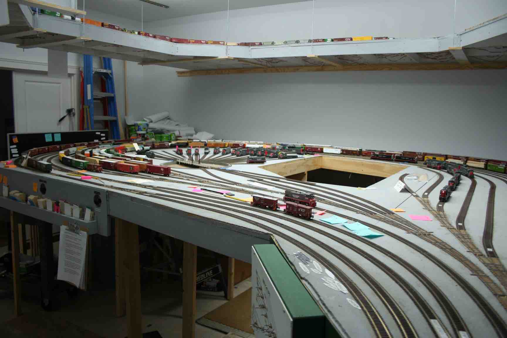
I began by roughing out dimensions for the shed.  I do not have accurate plans for the shed and needed to estimate everything based on a modest set of photos.  I very quickly discovered that although my track spacing for the engine facility seemed generous when fully exposed (not covered), I likely will need to increase the track spacing from 15 scale-feet to more like 20 scale-feet.  This is based on both the appearance of the completed mock-up in position and from careful study of a couple of the photos showing the geo-East end of the shed with the stub-track wall.  


With rough dimensions, I began construction of the roof.  I used triangular end pieces and an identical middle piece to help form the roof pitch.  These formers were separated by balsa strip out towards the long edges and a central foam-core spine.  More foam-core was used to form most of the remaining roof between the spine and the roof edges.  These were incomplete panels as the foam core has real thickness.


Roof section formers composed of chipboard end and center roof pitch formers, foam core center spines and balsa strip edge formers.


I then turned to making post assemblies using Evergreen styrene strip.  I used 0.060 x 0.080-inch strip for the posts and 0.040 x 0.12-inch top and bottom plates.  I started out placing the posts at 20 scale-feet intervals, but a check of photos sent me back to add more posts for 10 scale-feet intervals.  This was one of many brain “interruptions” during this model effort.  I also added longitudinal strips to hold the roof-edge side wall sheathing and a couple of other long beams seen in photos.  I think the “beams’ may actually be steam lines on two of the post assemblies.


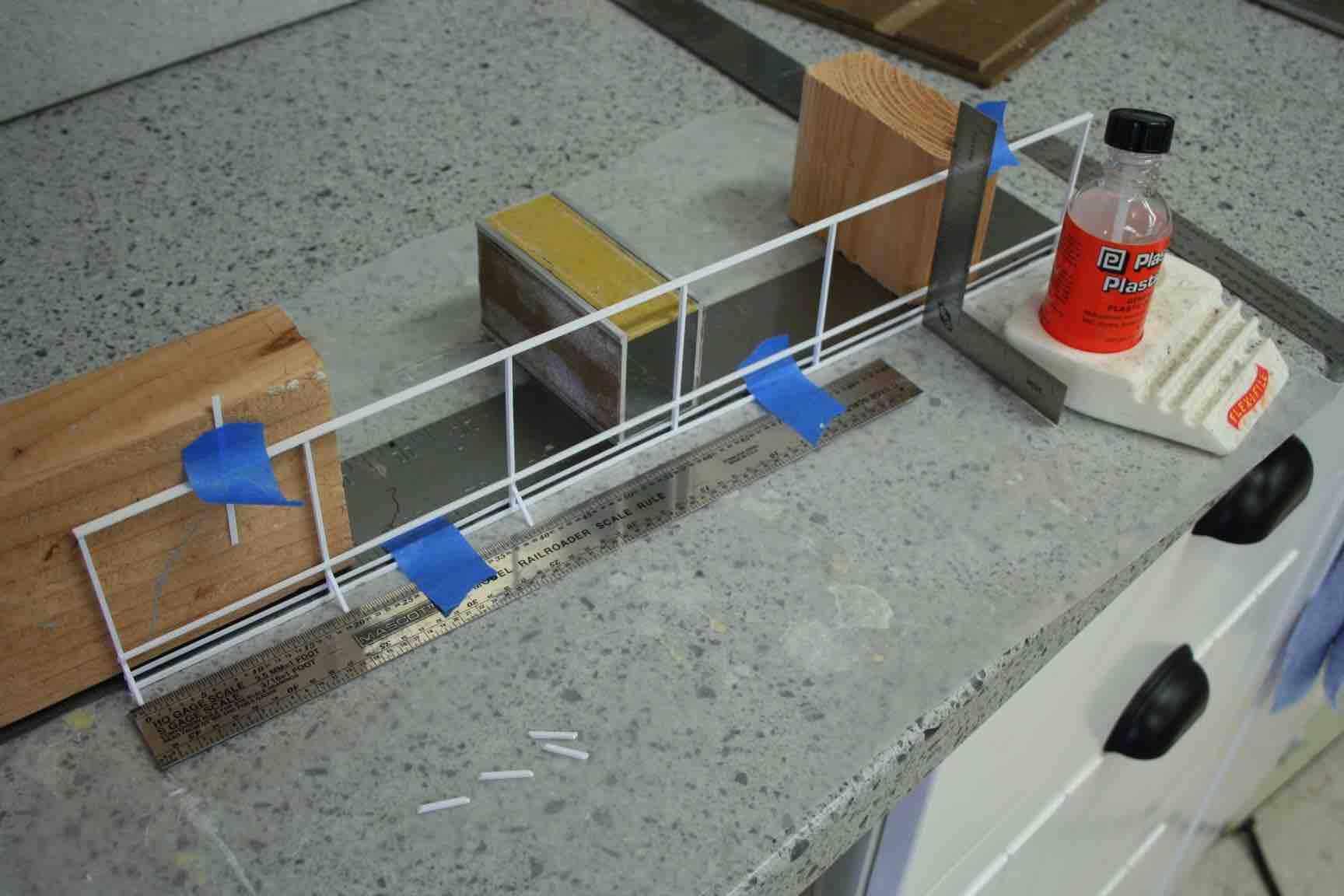
Post assembly construction, here with 20 scale-feet post spacing.


One feature seen in photos are knee braces just under the roof trusses, presumably keeping the posts square to whatever roof truss structure was used.  I used my NWSL Chopper with a jig piece set to help make 45-degree end cuts on same-length knee braces.


Cutting knee braces with an NWSL Chopper.  The cutting jig width on the other side of the chop blade was cut to 3 scale-feet wide.


I attached the styrene post assemblies to the wood roof spans using canopy cement and a bit of gap-filling CA adhesive to set several of the posts in position quickly and at the desired square joint.


Attaching the outer post assemblies to the roof sub-assembly.


At this stage, I was glad this was a “mock-up” as my placement of several of the cross-roof-spans was imperfect.  A final model will need to have real roof trusses that join precisely to the posts.  What I have is good enough for the mock-up and certainly conveys the open framing seen in photos.


When I sheathed the roof assembly with sections of “corrugated” image printed onto cardstock, I chose to augment the glue-stick adhesive on the cardstock with a brushed-on coat of thinned white glue on the subroof.  This was a BIG mistake!  The various bits of cardstock in the assembly—likely the foam-core sheathing—tightened up as the glue set. The result was a “pagoda” roof that bowed up on the ends.


Initial roof sheathing.  Close inspection will reveal the end posts have lifted up relative to posts more in the center of the structure creating a “pagoda roof” effect or a rocking structure.


I tried to correct the bowing by inverting the structure and applying another thinned white glue wash to the underside of the roof.  This did not cure the problem and created a second problem of printed image bleed at the roof peaks (lowest points on the inverted structure….).  I finally settled upon slicing each roof panel section (every ten scale feet) with a razor saw and then inserting cardstock into the gaps.  This seemed to straighten out the structure, but some bowing remains end-to-end.


Correcting the roof bowing.  The green splotches along the ridgelines are from the first correction attempt using diluted white glue on the roof assembly underside.  Cardstock spacers inserted into razor saw cross cuts were my second straightening attempt.  With the shed assembly seemingly straight, I applied new roof sheathing.


I assembled a wall for the stub track stall by laminating corrugated image cardstock back-to-back.  I cut into this for the window seen in photos and then applied an impression of framing on the inside wall.  


I learned a lot as I built this structure.  Adjustments to the track layout are called for.  I need to sort out how to properly frame the roof.  At least 51 roof trusses are implied by the number of roof posts seen in pictures.  I need to figure out what spans between roof trusses.  I also need to locate a suitable corrugated sheathing material—something that attaches well to the structure framing.  


For now, I have a mock-up that conveys the major features of the structure.  It may need to last for quite a while…


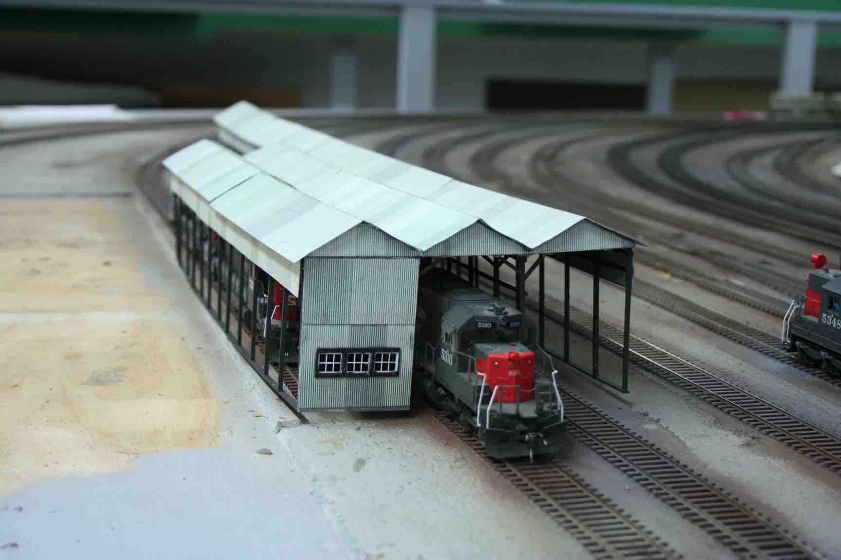
Oakridge engine shed detailed mock-up.


Tuesday, November 29, 2022

EUGENE YARD DESIGN AND OPERATION

A recent discussion with a fellow layout owner focused on yard design and operation.  I realized that discussion documented where I started with my Eugene Yard design and what it developed into.  This description begins with a look at the prototype and then works through several key elements I wrestled with during the design phase.  My yard design was enough to get me started on construction.  Once a crew of model railroad operators began working with that physical plant, the operations developed.  A significant track modification took place during the Covid-19 lock-down, albeit one suggested to me at the first full operating session.  


Prototype Eugene


Upon completion of the Natron Cutoff in 1926, Eugene developed into the major terminal and classification point on SP lines in Oregon.  This was reinforced in 1958 by construction of a hump yard at Eugene.  The historic Eugene Yard dated to Oregon & California days and the construction of the Coos Bay Branch.  The yard was perpendicular to the north-south mainline and along the line to Coos Bay.  It survived into more modern times as the Blair Street Yard which served as the local industry support yard.  That function and its location separate from the main yard location serves as the prototype inspiration for locating my classification yard alongside the Eugene Depot tracks, separate from the large staging yard formed by the reverse loop tracks in the “back room” of my basement.  


The Eugene Depot area had the WP Siding immediately in front of the depot and the mainline next over—a common SP practice.  Further removed from the depot were three tracks (I used only two) serving as the “City Yard” in support of industry in the immediate area of the depot.  A side note here—the “WP Siding” was named for the construction company that built the Coos Bay Branch: the Willamette Pacific.


Layout Design


I struggled with my base yard design.  While inspired by Eugene, there was no way I could fit in or operate the prototype facility that ran 6.5 miles north from the RR-West switch just before the depot out to Irving at the end of the hump yard and the main arrival-departure tracks.  Further, the prototype facility grew to something like sixty tracks wide across the hump yard and arrival-departure tracks—way beyond arm reach in HO scale!


A key design principle from the beginning was that the overall railroad needed to be operable by a crew of only six while still providing “satisfying” operations.  I observed through the years that even the most popular model railroad operations could go through periods where the available crew was less than the desired number for “full” operations.  This helped me keep my base yard design in check.  It was all too easy to keep adding tracks.  With that design objective of a six-man crew, only one would be assigned to the yard.  Even with that, I ended up devoting about a third of my RR space to the Eugene complex.


I went through an evolution wherein the primary yard was located in my “back room.”  That was not quite a stub-ended terminal—but close.  It had only a locomotive-set (think four-unit F7) tail at the far end of the yard.  The critical design breakthrough came during an email discussion with a good friend in California wherein I recognized I needed to be able to turn full train consists—notably the passenger trains--DURING an operating session.  I previously had figured out a connection through the spine backdrop near my current Willamette River bridges (think Siskiyou Line splitting off the main at Springfield Junction) that could reverse whole trains outside of operating sessions.  In a flash of recognition, I realized the base yard needed to employ a reverse loop, just as the top end already had in my planning.  That led very quickly to the current arrangement.


I recognized an arrival-departure yard could look a lot like a staging yard, hence the “back room” reverse loop staging became designated as the Arrival-Departure Yard.  Over time and use it truly has become that for the mainline.


Eugene Arrival Departure Yard.  The A-D Yard has twelve reverse-loop tracks.  These surround the engine facilities, with the turntable and future roundhouse site to the left of the operating pit and the diesel servicing tracks to the right of the pit.


Meanwhile, I still needed to facilitate classification work to serve the local freights serving the modeled industry.  That led to my placing an eight-track double-ended yard in front of the depot.  This yard is slightly shorter than the design standard for mainline trains (20 ft clear between siding switches), but the function supporting local freights “should” result in shorter trains.  Both ends of this yard have switch leads, although the RR-West lead is not quite as long as the classification yard body tracks.  This has not been a problem, especially with two switch crews working opposite ends of the yard.


Eugene Depot complex.  The Amtrak passenger train is on the mainline in front of the depot.  Between the depot and the mainline is the WP Siding.  The two-track City Yard is in front of (from an operator perspective) the mainline.  The eight-track Classification Yard is in front of the depot tracks.


Yard Operations on the HO scale SP Cascade Line


A normal full yard crew for my railroad currently consists of five positions:  a Yardmaster who directs action at the Classification Yard and oversees the Eugene City Switcher (when called), a West (classification) Yard Switcher, an East (classification) Yard Switcher, the “Santa Clara Tower Operator” (this is actually more like the A-D Yardmaster), and an Arrival-Departure Yard Switcher.  The Eugene City Switcher is a sixth position, run only when the Eugene traffic has built up enough to call it (usually every other or every third session) and with a large enough crew-count.  When I backdate operations into the steam era, a Hostler will be added to the A-D Yard crew.  Yes, the yard crew just keeps growing.


Yard functions break down to the Classification Yard handling cars in- or outbound to modeled industry (Eugene, Springfield, Oakridge/Westfir) while the Arrival-Departure Yard deals with the over-the-road traffic.  Yard transfers move traffic between the two yards.  The classification yard is expected to make up blocks of cars headed to the designated blocks/trains/directions.  In my current 1984 era, these are Los Angeles, Roseville, Ogden, Oakland, and Portland (plus other Oregon locations).  Note that from the 1960s on, with a major hump yard at Eugene, the SP originated full trains from Eugene to each of those destinations.  I will need to rework this operating plan when I back-date into the 1950s, as an SP blocking instruction booklet is available on-line showing the earlier operating plan.


The Arrival-Departure Yard begins each session with a mix of trains already built (perhaps awaiting loco and caboose assignment) and other trains yet to be built to the standard tonnage (car count/length) requirement.  A number of the tracks in the A-D Yard have semi-permanent destination designations.  Cars for those trains get added to the “rear” (arrival end of the loop) of those destination tracks until meeting the tonnage requirement, whereupon a caboose is added and the process for yet another train starts over behind that caboose.  


The Classification Yard builds and breaks down the local freights.  The Yardmaster has tag labels that fit between the rails to help him designate and communicate that designation to the switch crews.  The class yard has eight tracks.  Often the YM will assign multiple destinations to those tracks until the car count builds to a point needing separate designation.  Although I intended the City Yard tracks to serve only the Eugene industries, my crews and I quickly found those tracks very handy serving as the A-D tracks for locals.  Since the Eugene City switcher is one of those locals, it still works out.


Action at Eugene.  A RR-West freight is on the WP Siding directly in front of the depot.  Coming into Eugene on the mainline in front of the depot is a RR-East train.  This “left-hand running” arrangement fits with the track arrangements into and out of the A-D Yard.  The City Yard tracks are unoccupied.  The Classification Yard crew is hard at work with Yardmaster Rick A. in the foreground checking car cards in the slot boxes for each yard track.


Low Crew Count Operations 


I now have considerable experience operating with a low crew count thanks to the pandemic and affiliated lockdowns and subsequent tentativeness on crew response to the crew calls.  I never imagined that such would be the cause of needing to deal with lower than desired crew counts.  A key for this is to maintain a balance of traffic.  Think of it as an economic downturn or other low business cycle.  Fewer trains are run.  Yard operations expectations are reduced.  More of that work is pre-staged.  I have already indicated that the Eugene City Switcher is called conditionally—when a big enough crew is present to staff that position. 


I have yet to formally plan for the reduced road crews, handling it ad hoc.  My standard full crew provides for five road crews and two helpers.  I intend creating an alternate plan for three road crews and one helper.  An additional option on the helper return to Oakridge is to leave them on the Beattie Spur at the Summit for pickup by the next RR-East freight to be placed on the point and have that crewmember/engineer operate two throttles (easier than adding more locos to the consist).  We have experience with this during the last two and a half years.


With low crew, annul trains and combine functions of the remaining trains.  


Blocking Instructions


Note that Eugene was an originating terminal in my current 1984 time-frame.  As such, only a few trains run through to or from Portland (RR-East of Eugene).  Those are all First Class or equivalent and are not modified at Eugene.  They get assigned to the outer loop tracks in the A-D Yard.  Earlier era operations will take some thinking and development as to how to add or delete blocks, but what I see in the SP blocking instructions points me toward blocks added or removed from the rear of their trains.  This is very similar to my current practice of RR-Eastbound arrivals at Eugene having the Eugene empties at the rear and any Eugene (and up to Oakridge) propers (cars headed to customers served by that yard) as the next block ahead.  


A BRLAT (Brooklyn <SP Portland Yard> to Los Angeles Trailer) train leaves Eugene A-D Yard Track 1.  The outer (lowest numbered) yard tracks represent tracks to and from Portland.  Other trains with locomotives already assigned can be seen on a couple of the higher-numbered tracks to the left.  These are trains that originate in Eugene and are set to depart.


Very Low Crew Count Operations 


With very low crew count (below ten) I end up with just the Eugene Yardmaster and maybe the Santa Clara Tower Operator.  Both then take on the role of footboard Yardmasters and handle a throttle.  The Eugene Classification YM usually takes one switch engine and uses it exclusively, working back and forth between ends of the yard as necessary.  Habitual track use has the front track (Class-1) as the run-through track or otherwise as the slough track.  An alternative is to run through using a City Yard track.  All such Yardmasters have had no problem working this out. There is no need for a helicopter or other crew van to work opposite ends of the yard.


Summary


I had a fair bit of model railroad yard operating experience when I began the design of my layout.  Even with that experience, I struggled with the design for my base yard complex.  Identifying the functions helped the process.  Establishing a requirement for “satisfying” operations even with low crew counts helped keep the size of my yard in check.  The issue was one of balance between the yard operations and the rest of the layout—both over-the-road traffic and local industry switching.  That balancing act established the physical arrangements for my Eugene complex.  


With the physical plant established, the operating plan developed as I brought in experienced model railroad operators. While I provided an outline of my expectations for their work, I let them decide how they would accomplish it.  Along the way, suggestions were made to improve the physical plant—notably the addition of a second main track between the depot and the Arrival-Departure Yard (departure end).  Other suggestions and comments led to the development of the current operating scheme.  That scheme balances the physical plant with the work being done.  This remains a work in process as fresh ideas emerge, are tried, and, if successful, incorporated.


Friday, October 28, 2022

EAST SPRINGFIELD—AGAIN

Over the course of time and frequent operating sessions, one finds certain spots on a railroad that need extra attention. While I strove to build and lay track with care, I still have spots that confound my attempts to make them operate reliably well.  Such has been the case with my track at RR-East Springfield.  The switches installed there were among my very first that I built using Fast Tracks tooling and the first track I laid permanently.  Therein lies the likely source of my problems.  This spot has drawn repeated “fix-it” notes and several serious attempts to correct the perennial derailment issues.  I documented one of those previous efforts with:

https://espeecascades.blogspot.com/2019/01/track-realignment-at-springfield.html


RR-East Springfield.  Track issues keep showing up in the two switches that are part of the mainline through this area.


In spite of my previous efforts, I continued to have problems in this area.  Taking another close look aided by a different selection of reader glasses, I spotted a funky almost-kink at the insulated track joint just beyond the points of the RR-East-most switch.  I attacked that problem by soaking the adhesive caulk holding the track with alcohol (50/50 rubbing alcohol is sufficient) and then lifting and resetting that track to eliminate the track joint issue.  The alcohol softens the caulk, but when allowed to evaporate, the caulk usually reforms to provide at least some bonding.  I added spikes on both sides of the insulated joint and made sure the joint was filled with styrene and filed the rail and joint smooth.


I then cross checked the switch geometry with a NMRA gauge.  While everything appeared in gauge, I took the opportunity to adjust the points a little.  Fast Tracks normally recommends a minimum clearance gap between the open point and the stock rail.  I have found my equipment (dominated by six-axle road locomotive) benefits from having a bit wider gap.  I recently found the awkward switch location up at Crescent Lake had too much distance between the frog and the frog guard rail.  I double-checked that, but this pair of #8 switches appeared to be fine.  Still, it was worth checking.


Reworked track at RR-East Springfield.  Note the short section of straight track just beyond the points.  This is some of the original track.  Just beyond that is the unpainted replacement track forming the curve.


While I was working in this area, I decided to try to reform the cork roadbed for the ballast slope.  That had been upset when I re-laid the curve leading into the switches back in 2019.  I tried using my finish router with a 45-degree bit.  While this helped form the ballast slope, it was hard to control.  I added a temporary edge guide—a piece of styrene taped to the base plate of the router.  The combination of that plus a very awkward work location led to me damaging some of the track.  That lead to pulling up most of the track curve and replacing it with a new section of flex track.  At this point the project was getting deeper and deeper into difficulty—far more than I expected with a “simple” track fix.  


Cutting the ballast slope into the cork roadbed at RR-East Springfield.


Cutting the ballast slope.  Note the wandering router cut.


I finally chose to leave the ballast slope cut for another day.  I critically needed to get the track back in service for another operating session in early November.  That session will show me whether I have finally cured this headache.

Sunday, October 16, 2022

OlyOps 2022

As we reemerge from our cocoons of the past couple of years, regular model railroad events are throttling back up.  OlyOps returned in mid-October.  This was a single-day local-regional operating event, drawing on “Boomer” operators within roughly 200 miles of Olympia, Washington.  Organizer Greg Wright has a well-polished routine for this event starting with a good selection of operating model railroads around Olympia, combined with a guest list built up over the years that invites operators from around the Pacific Northwest.  


The 2022 OlyOps featured eight local layouts (the typical number of layouts used).  Thirty-eight guest operators participated.  The event was arranged such that each Boomer (guest operator) operated on one layout in the morning and one layout in the afternoon.  Layout assignments were made by the Registrar with no preferences considered.  Layout assignments were picked up either Friday evening or early Saturday morning. 


The registration “fee” for the event was either canned food donation for the Thurston County Food Bank or a cash donation to same.  This year’s event raised $650 and eight very large bags of canned goods—a super response!  


Three of us carpooled up to Olympia from Oregon—regular operators on my railroad as well as me on theirs.  We were assigned as a carpool, so we worked on the same pair of railroads.  


Our morning assignment was on Scott Buckley’s Tehama Valley Railroad (TVR).  I previously operated there during a SoundRails event and was delighted to have a return visit.  Scott’s TVR represents a shortline in the California Sacramento Valley that runs east from connections with the outside railroad world at Hamilton City to locations east of Chico.   Separate interchanges with the Southern Pacific and the Northern California Traction Company (Joint ATSF and WP short line) are worked by TVR road crews.   TVR traffic includes produce and lumber shipped out via the Hamilton City interchanges.  


Craig L. works our train across the valley to pick up loaded produce and deliver fresh refrigerator cars at Walnut Grove on the right.  In the background is the bridge across the Sacramento River and on the left is the town of Colusa Junction..


The TVR is still under construction, but the basic operating pattern is well-established and supported by trackwork.  The layout is about half “scenicked.”  Structures include both kits and a number of scratch-built industries, notably the produce packers and other agricultural businesses.  I look forward to return visits.


Another crew works a less developed area representing Butte City in the middle of the layout space.  The Hamilton City interchanges are seen in the back-right of this view.  The railroad terminates at its east end at a turnback loop (unseen on the right) after passing through the lumber town of Oakville.


Our afternoon session was with Chuck Ricketts on his Baja Siena Railway.  This was a fanciful On30 layout set on an island off the northern Mexico coast.  Our operating session was scheduled to be the last formal session on the railroad in its current location.  Chuck sold the layout to Paul and Nancy O. who were on hand to assist and serve as one of the operating crews.  They will partially dismantle the layout and move it to their home in Seattle.  


Craig L. and Jim E. work the base yard and car float.  The mine tipple with live loads (steel ball bearings) where I worked is barely visible on the left.


Vic N. and Jim E. work the major town and industry area on the other side of the layout.


Chuck Ricketts began construction of the railroad until slowed by a major health event, whereupon Jim E. took over to complete track laying, wiring and generally assisting to bring the railroad up to its current state.


Though fanciful, the railroad proved a lot of fun to operate.  Four crews were kept active through the afternoon.  


OlyOps concluded with a dinner at the community golf course, attended by both the local crew and visiting operators.  We all had a great time and look forward to next year’s edition!

Sunday, October 2, 2022

RICK KANG

With a heavy heart, I report the passing of another of my great railroader friends, Rick Kang.  Rick served as a Dispatcher for the Southern Pacific at Eugene from the 1970s until that office was closed and consolidated to Roseville in 1989.  Throughout that time and later, he was a tremendous resource on railroad operations for the model railroad and railfan communities.  


From my time in the San Francisco Bay Area, I knew of Rick’s involvement with Jim Providenza’s Santa Cruz Northern model railroad in the North Bay area.  Being based in the South Bay, I never had the privilege of operating with Rick at that time.  Instead, when I retired and moved back to Oregon, I met Rick through operations at Tom Dill’s SP Siskiyou Line layout. 


Rick was immediately interested in my efforts to model the SP Cascade Line.  Rick was generous with information, time and effort to help bring my dream into reality.  He dispatched my first operating sessions and taught that art to my core group of laymen model railroaders.  Although I was experienced in the art of model railroad operations, Rick helped raise my and my crew’s knowledge and practice on my railroad.  Often times, Rick would arrive for an operating session with an envelope of new paperwork and instructions covering yet another facet of rail operations.  


Rick Kang dispatching my SP Cascade Line in June 2016.  The railroad was in raw shape with the Dispatcher situated in an area eventually covered by the crew platform for Crescent Lake.  The step ladder was used to access the Crescent Lake control panel.


Rick Kang advising and John B.—teaching laymen model railroaders the fine art of railroad dispatching.


Rick Kang interacting with Dispatcher Dave H.  The Dispatcher’s desk moved into our exercise room and gained a steel panel with track schematic.  By this point, Rick had trained several Dispatchers for my SP Cascade Line and had transitioned to a new role as Assistant Chief Dispatcher.  I didn’t know I needed one until Rick showed us the value added.  The ACD interacted with both Dispatcher and train crews, keeping the railroad moving while the layout owner chased gremlins.


Rick Kang added to the crew briefing, training all of us into better procedures.  Here he is reviewing proper radio procedure.


Rick Kang interacts with train crewman Jim L. in Rick’s role as Assistant Chief Dispatcher.


Rick was bright, focused, and always thinking about how to make model railroad operations more interesting and realistic.  For me, he was a mentor and friend.


Rest In Peace, Rick.

Thursday, September 29, 2022

AWKWARD SWITCH MAINTENANCE

In spite of good intentions and even fairly good execution, the design of my railroad inevitably produced a few difficult locations for track maintenance.  My September 2022 operating session emphasized the critical need to attack one of those tight space maintenance tasks.  My Crescent Lake staging yard features twelve tracks within a reverse loop.  The turnout ladder for the “West” end of the yard extends beneath the basement stairwell as the track passes from the main room to the “back” room where both levels of staging reside.  The switch for the number two track had caused trouble in June.  I thought my bit of work on this switch had fixed the problem, but the September session proved otherwise.


The Switch for Westbound entry to Crescent Lake Track Two is located just above the yellow track cleaner box car and alongside the reading glasses.  Note the stairwell covering descending from the ceiling to the right.


I pulled out my track tools and a step ladder.  I had to closely examine the troublesome switch in a very awkward space, some 7.5 feet above the floor and under the stairwell covering.  Close inspection with added lighting, vision enhancements, and an NMRA gauge quickly showed two problems.  The first was that the points were not throwing all the way over for entry to Track Two.  The second issue was too wide a distance between the guardrail on the stock rail for the frog and the frog itself.  For both problems, I can only note that things change over time, as neither had been an issue until recent operating sessions.


Having identified the problems, the solutions were relatively straight-forward, albeit accomplished in the tight space.   The frog guardrail required a simple application of soldering iron heat and a slight shift of the guardrail.  


The offending guard rail is pointed to by the needle nose pliers and tweezers.


The switch machine required opening up the main wiring termination panel for Crescent Lake.  I was able to slide the Tortoise by Circuitron™ switch machine fulcrum tab downward on the machine to increase the throw-rod throw.  With increased force on the points I added spikes on the outside of the stock rails at the points to help keep the rails in place.


This low-light, jiggled picture illustrates the problem of getting into the switch machine for adjustments.  The switch machine is the green block with a yellow label up under the maze of wire.


My staging and track cleaning efforts through this switch indicate my repairs were successful.  This is all part of what it takes to have an operating model railroad.

Friday, August 26, 2022

TREES FOR THE FOREST—ROUND TWO

Casting about for summer projects, I decided to tackle more trees for my forest.  I settled upon “furnace filter” speared onto trunks as my basic construction technique for Douglas Fir—the dominant tree in Western Oregon.  I described the technique in my first post on this topic:

https://espeecascades.blogspot.com/2018/12/o-tannenbaum.html


I settled on using tree materials from Coastmans Scenery Products:  https://www.coastmans.com/  Coastmans supplies finished trees, tree kits and separate materials:  trunks and branch material.  So far, I have just used the kits, but am about to move to using just the trunks and branch material (mat) as I don’t need much of the other material in the kits, at least for trees well into my forests.  


My first efforts toward making Douglas Fir models were a bit disappointing.  Following instruction by Roger Rasmussen at the 2018 NMRA_PNR Convention in Portland, I split the branch mat material into thin slices before gluing them to the tree trunks.  My efforts left a bit too much space between the disks such that the trees really did not capture the bulk of foliage I see all around me here in Oregon.  That left me disappointed and led to the long wait until this second effort.  As with most artistic ventures, one learns by doing.  I just needed to move that process along.


My earlier blog post (O Tannenbaum!) describes the basic procedure, but I will briefly recap here.  Working over oven pans to capture and control the ground foam that sheds from the branch material mats, I tore suitably sized “disks” of material.  Actually, the “disks were more like squares, but they get further shaped by tugging on the mat material and later trimming it on the developing tree.  I used an awl to poke a hole in the center of each “disk” and then slid the disks down onto the trunk, gluing them in place with white glue.


Making trees.  Working over oven pans helps corral the ground foam shed from the branch material mats for reuse as flocking.


Once the branch material glue sets, further trimming with scissors helps shape the tree.  Spray adhesive is applied and then the ground foam is sprinkled liberally upon the tree “branches.”  Upon reflection, my first effort spaced the branch disks a bit too far apart.  I also did not apply quite as liberal a coating of ground foam as I did on this second round.  As I expected, I needed to augment the flock from the tree kits with more ground foam.  Coastmans uses Woodland Scenics Conifer green Coarse Turf (T1366) on the branch mats, so it is easy to augment the ground foam supply.


Flocking the tree branches.  The three trees on the left have been flocked.  The three on the right are ready for flocking.  Note the space between the thin branch disks on the second tree  from the right.  The flocked trees had similar gaps.


The trees for Round Two.  Most are nine inches tall.  The two in back are eleven inches tall—still short for old growth Douglas Fir.  Both are suitable for layout scale.


I am much happier with my second effort at tree making.  The keys to success were a bit closer spacing of the branch mat disks on the trunks and a more liberal dusting of turf “flocking.”  With this success, I am ready to start my production line.  Think thousands of trees….