A chronic operating headache has been the RR-East Switch at Springfield. Most every operating session has generated at least one trouble note on a Post-It ™. My six-axle road locomotives just kept stumbling--derailing--at this switch. Try as I might, I just could not identify the problem. It took the experienced craftsman eyes of one of my regular operating crew to spot the cause. He found my mainline track kinked relative to that East Switch.

The RR-East end of Springfield with lots of trouble notes at the troublesome mainline switch.

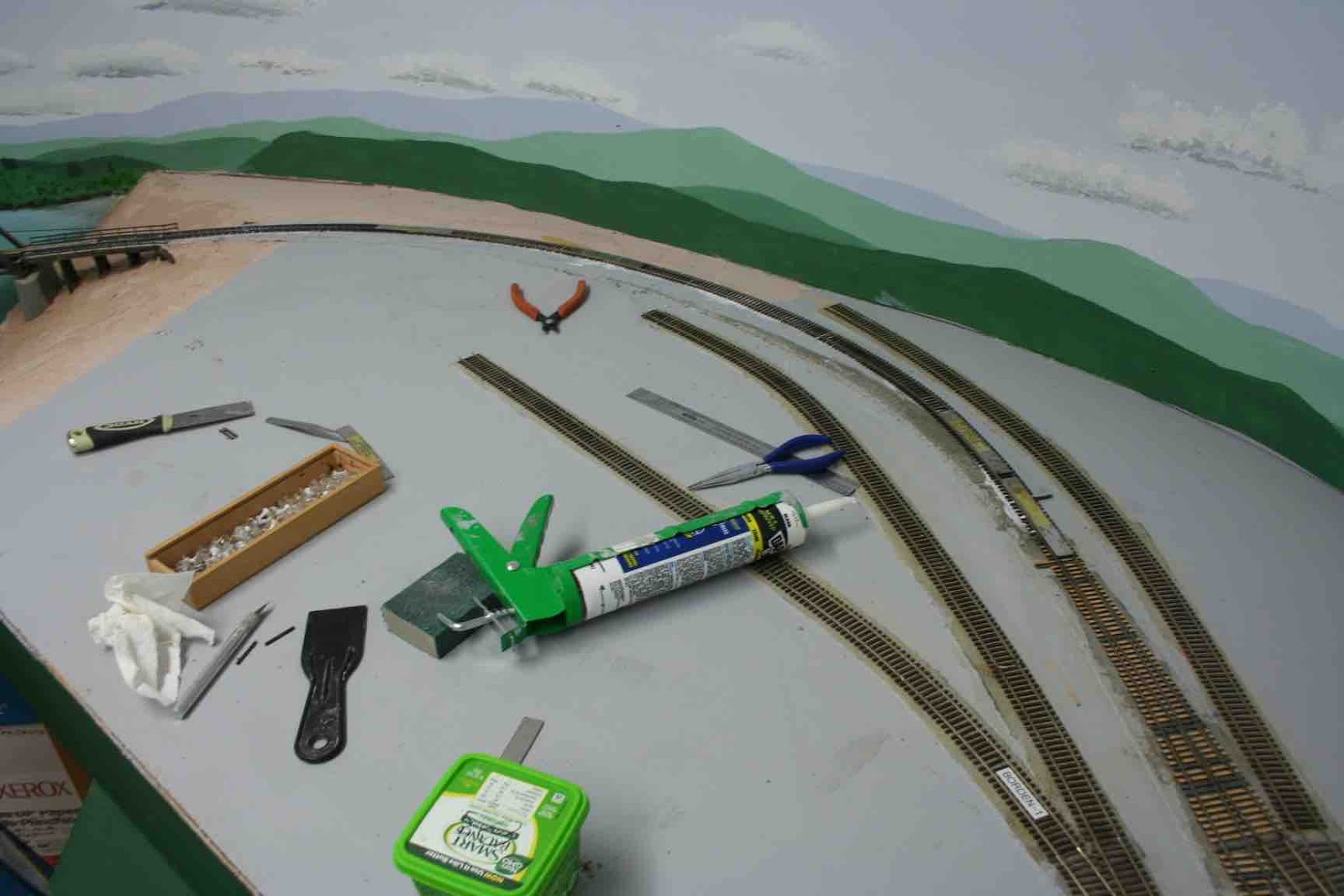
The kink in the mainline alignment entering the switch becomes a bit more evident when a straight track tool is aligned with the straight route through the switch.
Several correction techniques were suggested by my craftsman and myself. These included ripping out the switch and putting in a new switch. This was suggested by the fact that the Springfield mainline switches are the earliest examples of switches I built using Fast Tracks tooling. My craftsman friend suggested I try relaying just the stock rails, one at a time, leaving the rest of the switch in place. While tempting, I resisted for a couple of months--and operating sessions. Finally, I decided to remove the mainline track RR-East of the switch in preparation for either replacing those stock rails or realigning the mainline.
The stock rail replacement and even the switch replacement options were attractive as my current thinking about track laying suggests building switches with extended stock rails. This would result in hand-laying (spiking) those extended stock rails into a better easement into the usual curves on my railroad. This is one of those "lessons learned" that one acquires over the course of building and operating a model railroad.
When I loosened the mainline track from the roadbed, I found I still had a firm joint formed by the insulated rail joiner and gap filler that formed the joint between the switch and the mainline flex track. Insulated gaps isolate mainline switches such as this one to create OS blocks for my planned CTC system. While I could break that joint, I decided instead to exercise my third option--realigning the mainline track.
Realigning the track required a broader sweep to the curve leading to the Willamette River Bridge than originally laid. This required expanding the width of the cork roadbed. I expanded the roadbed by gluing another piece of roadbed to the outside of the curve upside down to match the existing roadbed profile. Once the glue set, I shaped the new cork to the old roadbed using a Stanley Surform ™plane and sanding blocks. This also cleaned off most of the remaining residue of the old adhesive caulk used to lay track. I found myself adding more and more roadbed extension as I worked with the mainline track to form a new curve with easements at the ends. I eventually pulled up and realigned all of the track between the troublesome East Switch and the Willamette River Bridge.

Roadbed width expansion underway with new cork roadbed glued to the outside of the curve. The new piece is upside down to mate the roadbed edge slopes.

Expanded roadbed shaped to match the thickness of the existing roadbed.
I reformed--realigned--the flex track, adding an additional short section in the middle to account for the now slightly longer track alignment. I pulled out my Ribbonrail ™track gauges to help the realignment. I began with one of my ten-inch straight gauges at the bridge end and used the five-inch gauge at the switch end. I then used a 48-inch radius gauge at the switch end to help create a better easement into the curve. The bridge end was formed by eye, though checked with the broader curve gauge, as well. I was pleasantly surprised to find I could form the major portion of the curve using my standard 42-inch curve gauge. I expected I might need to tighten the curve to 40-inch radius, but I was able to maintain my mainline standard of 42-inch radius.
Finally, it was time to apply caulk and glue it all back into place. The Ribbonrail ™track gauges were left in place at the ends and at track joints as the caulk set. I also held down the track with my standard method using cans of baked beans (or any other canned goods).
Realigned track in place with track gauges ensuring critical spots maintain the desired alignment.
New track electrical feeder holes were drilled for both the existing feeders (pulled out of the way during track-laying) and new feeders for the new piece of track placed in the middle of the curve. This maintains my construction standard of a feeder soldered to every piece of rail.
Finally, the moment of truth arrived to test out the new alignment. I ran several of the most troublesome locos over the new track alignment. Most of the trouble tags identified the loco that derailed--an important part of the troubleshooting process. Many of the chronic offenders were SD45T-2 models. I have no explanation for why these and not the equal frame-sized SD40T-2s or of the other SDs with the same six-axle truck dominated the tracking problems. I just accept that those were the troublesome units. A final check was done with an EULAT train I needed to re-stage up to Crescent Lake for the next operating session. This added 89-ft. autoracks and TOFC to the mix. I am happy to report all have passed through the reworked track just fine. The next operating session in a couple of weeks will be the "acid test."

An EULAT passes through the reworked curve and approach to the RR-East switch at Springfield. Success!
No comments:
Post a Comment