Friday, December 31, 2021

RR-EAST EUGENE DEVELOPMENT – 5 – Skillern Oil

My development of the new industrial district at RR-East Eugene continued with Skillern Oil.  Skillern Oil was a family-owned fuel oil dealer in Eugene for many years.  It was suggested to me by one of my long-term regular operators who lives in Eugene.  Skillern supplied their home heating fuel oil.  Good enough for me—an historic connection.  


I have taken considerable liberties in my development of Skillern Oil as a bulk fuel and oil dealer.  A number of these were along the tracks between the depot and downtown area and the main yard complex for the SP.  During the late 1960s and early 1970s I recalled seeing these bulk plants on my way into downtown Eugene.  They are long gone, as oil product distribution has taken a different form using pipelines and trucks these days.  Those petroleum product dealers were still a function into the 1970s.  I chose to have my Skillern Oil stand in for the several bulk plant dealers.


My Skillern Oil draws from two principal sources.  The warehouse and office flat were built from Walthers “Clayton County Lumber” kit (933-2911).  Other than turning the office into a building flat to be mounted against my basement wall, these were easily built.  The oil tanks and future details were from a pair of Grandt Line kits (#5907) for “Midwest Petroleum Distributors.”  Unfortunately, these Grandt kits are long gone, with reports the mold for the tanks suffered significant damage long before the Grandts retired and sold their business.  Still, I stockpiled these kits long ago, knowing they were very typical of oil bulk plant tanks nationwide.  It was now time to use them!


Skillern Oil under development with the major pieces in place.


The Grandt Line tank kit comes with three tanks that can be built as either vertical or horizontal tanks.  I chose to model a cluster of four vertical tanks and one horizontal tank.  A quick study of bulk oil plants showed this as a fairly typical arrangement.  I did not have space for a second horizontal tank, so I now have one spare.  I built the Grandt Line tanks per the directions.  The kit tank platform and ladders are designed for a pair of horizontal tanks, so I needed to scratch-build my inspection platforms.  This was done simply with Evergreen styrene, my go-to structure material.  


Inspection platform access ladders and tank clusters.  The ladders either face the wall or the modest space between the horizontal tank and the warehouse, but I know they are there.


I need to complete several details, all provided in the Grandt Line kit: a pumphouse, a tank car unloading rack, and the fuel delivery rack for loading tank trucks.  I still am trying to run down what major oil company Skillern was associated with, but it is not unusual for the tanks to have no signage.  I know they were not affiliated with Chevron (Standard Oil of California) or Shell, so no city roof sign on the warehouse.  For now, I chalk up another industry rendered into three dimensions for this developing area of my railroad.


Skillern Oil in the RR-East Eugene industrial district.


Tuesday, November 30, 2021

RR-EAST EUGENE DEVELOPMENT – 4 – EUGENE FREEZE

With track laid, wired and controlled, the next task in this area between the Eugene depot and the Arrival-Departure Yard was to begin populating the new industry spurs with industry structures.  First up was the nominally easiest structure—Eugene Freeze.  I chose to bash a pair of Walthers Cornerstone kits for their “R.J. Frost Ice and Storage” (933-3020).  I try to avoid using the very recognizable Walthers kits without modification.  In this case, all I did was extend the length of the building, leaving it very recognizable yet.  Still, I like the looks of this structure.  It fits most areas of the country, a common problem I otherwise have on the West Coast. 


Eugene Freeze ready for business.


The straight-forward modification for this kit structure extends it by doubling the middle pair of panels.  This was accomplished by making cuts on either side of the joining pillar.  Note to self—double-check which side of the pillar to make those cuts!  Dimensional control for the joints was achieved by measuring between the holes for the awning supports.


Building wall splices.  The caliper was set to the distance between holes for the awning supports in the middle of the pillars.


Once the long walls were joined, the rest of the construction proceeded per the kit instructions.  I needed to remember to prepare enough parts like the loading doors for the extended structure.  I also spliced parts for other parts affected by the longer side walls such as the roof, loading docks, and awnings.  The site for this structure on my railroad is not as deep as required for the full Walthers kit as designed with full awnings on both sides.  I chose to scratch build a narrower awning for the back side.  I may yet need to trim this awning and the rear loading dock.  


Rear loading dock and scratch-built narrow awning.


Structure finishing used various paint “rattle cans.”  The Rustoleum “Chalked” line is particularly useful as are various primers as they dry to a nice flat finish.  I followed up with AIM weathering powders.  Final assembly proved a challenge of maneuvering the structure and holding it as glue set.  A lot of the final assembly was done with canopy glue.  I remain undecided on the structure sign, so that will come later.


Cooling tower end of Eugene Freeze.


The first of the industries for the six new spurs has been placed and is ready for business!

Sunday, October 31, 2021

RR-EAST EUGENE DEVELOPMENT – 3

The battle to add a half dozen industrial spurs and a siding at RR-East Eugene has finally reached a functional stage.  The track has been installed and now wired. https://espeecascades.blogspot.com/2021/08/rr-east-eugene-development-1.html

https://espeecascades.blogspot.com/2021/09/rr-east-eugene-development-2.html

Switch machines have been installed and now the control panels have been wired and deemed functional.  This last electrical push has been yet another “electrical war.”


RR-East Industrial Siding and spurs completed and in service.  Note the headlight is on for the switcher!


“Simply” adding track, switch wiring, switch machines, and controls has been yet another frustrating “adventure.”  I have been painfully and frustratingly reminded that my original goal to have all of the primary construction completed on my railroad by the time I reached age 70 was a valid goal, mostly met, but now verified whenever a “modest” addition to the railroad is made.  Now a couple of years beyond that landmark age, I find it more difficult to crawl under the layout—and get back up—while vision has become more of an issue.  


On the vision point, I had cataract surgery a couple of years ago.  This imposed the full brunt of presbyopia upon me.  Previously, my extreme near-sightedness actually worked in my favor, as I could remove my glasses and find all within my arm’s reach in focus.  Post cataract surgery, I now must use some vision enhancement, usually readers.  An issue for under layout work is selecting the correct reader correction for the task at hand.  I am now VERY conscious of focal distance!  I note the issues of body flexibility and vision as a warning to others as they embark upon layout construction.  Tailor your plans to your abilities.  I am doing ok, but frustrations show up now.


Once the track was laid for the new industrial zone, I needed to wire it.  I dutifully dropped feeders and attached them to the track power bus for this section of track.  Only after I had dropped all the feeders—but fortunately before I soldered them to the bus wires—did I finally attach my short circuit detector to the track or bus wires.  Argh!  I had a short circuit!  Best practice is to have that short circuit detector (it has a buzzer) clipped to the isolated bus wires as one starts connecting feeders.  That way one immediately identifies a short and can sort it out for correction immediately.  Instead, I was faced with after the fact trouble-shooting.


I was able to split the siding into two halves.  This greatly aided isolating the short.  I also pulled all of the feeders off the bus wire connections and started over.  I found the first of two shorts when I started hooking up one of the spurs.  Visual inspection did not locate the fault.  I then cut the pc-board ties used in this section in half, figuring I might not have gotten the proper gap cut into those ties.  That still did not remove the short.  I finally isolated the problem to a pair of feeders.  Closer inspection revealed I had used the reverse color code (red is supposed to be the rail to the rear in this area).  Instead of my usual practice of the past that connected feeders to the rails just beyond the frog of a turnout, I had moved further out on those now extended rails—to spacing that was very close to normal track spacing between a pair of feeders.  That is why I did not spot this fault when inspecting underneath the layout—it looked like all the rest of the normal track feeders.


The offending track feeders.  The feeder at the tip of the knife blade should have been a white wire.  The opposite feeder at the tip of the red sanding stick should have been a red wire.  I had reversed those wire colors.


I continued to reconnect feeders to the track bus wires.  In the second half of the siding, I found yet another short at a switch.  This time the solution was identified fairly quickly.  I had not gapped one of the pc-board ties around the frog assembly as completely as necessary.  This was evident from a close inspection from above and quickly remedied with a cutoff disk in my motor tool.  


Next up was installing switch machines.  I wire my Tortoise ™ switch machines with a tail leading to a terminal block.  I do this work at the workbench and then move to the layout.  In spite of needing to crawl under the layout and then check from above, I have found a system for installation that works for me.  It involves temporary installation of the machine using mounting screws loosely positioned and a double-sided tape pad on the machine.  Top side inspection reveals whether I must make any adjustments to the mounting or the throw rod.  Once satisfied, I tighten the mounting screws and move on. 


One of the switch machines required an offset mount.  Circuitron’s fulcrum plate for the Tortoise ™ has a center hole and offset holes.  My previous attempt to use the offset holes was not successful, so I developed an alternative mounting of that machine.  This time, I did not relish the thought of needing to rout out a longer slot for the throw rod—all from underneath in a tight location.  I decided I would give the alternate fulcrum hole another chance.  This time I was successful.  One change I made was to bend the throw rod back to a vertical orientation above the fulcrum plate.


Offset throw rod mounting for the left switch machine.  The right machine has the more conventional center fulcrum hole mounting.


Motivation for the offset switch machine mounting.  The left machine is part of the yard throat for the Eugene Arrival-Departure Yard—critical trackage.  This machine was NOT to be moved!  The machine on the right is the new machine, using an offset throw rod.


With the track wiring done and the mechanical work installed, I turned to the controls.  Yet again, I encountered a roadblock.  I installed toggle switches for track switch control.  I had to split them between two panels, as each panel corresponds to controls in a specific geographic area on the layout.  One panel’s switches proved straight-forward.  The other panel showed a short (not again!).  After trying several trouble-shooting approaches and consuming a couple of weeks thinking about this, I finally admitted defeat.  I removed the new toggle switches and their wiring and started over.  This time, I started wiring from the toggle closest to the connection to the twelve-volt supply for switch machines.  This approach worked.  No more shorts, but one machine would not throw.  After attempting to locate the fault, I finally just dropped the switch machine and replaced it.


Control panel wiring underway.


As seen in the first photo of this tale, the electrical gremlins have been beaten back.  I feel a bit battered and bruised and certainly frustrated, but it is finished!

Tuesday, September 14, 2021

RR-EAST EUGENE DEVELOPMENT – 2

I continue to work on the new industrial area at RR-East Eugene—just beyond the Eugene Depot area.  In my previous post, (https://espeecascades.blogspot.com/2021/08/rr-east-eugene-development-1.html) I described the primary track layout, fabrication and installation of switches and the track that completes the industrial siding.  The current effort might be described as, “Adventures in Track Laying.”


While the track and switches for the industrial siding were laid, more track work was needed to complete the track in this area.  Three tasks remained: filling in the blank spots in the tie blocks with pc-board ties, firmly fixing curves and transitions with spikes, and completing the industrial spurs.  


Track completed for the RR-East Eugene industrial area.


As noted in the previous post, I chose to extend the stock rails of the turnouts I fabricated, allowing me to complete all of the track needed for the industrial siding.  This replaced any need to fit flex track pieces between turnouts.  The rails for the turnouts needed to be trimmed to fit the space.  I used Fast Tracks QuickSticks ties to extend the track beyond the switch tie blocks.  These ties feature blocks of five ties separated by gaps intended for pc-board ties.  I needed to install those pc-board ties.


Before I installed the turnouts and their extended tie blocks, I removed the webbing between those blocks of five ties.  Unfortunately, I missed doing this for one of the turnouts—one with quite extended tie blocks.  That left me with needing to remove those webs after the turnouts and ties were glued (adhesive caulk) to the roadbed.  Ugh!  Fortunately, I remembered a Dremel cutter that could assist me.  Dremel High Speed Cutter 199 has a cutting teeth rim on a disk that is just under 3/8-inch in diameter and 1/8-inch thick.  These dimensions proved perfect for this job.  The cutter fit neatly between ties on either side of the gap and the thickness was just right for getting underneath the rail and above the roadbed.  Running my Dremel tool at modest speed, the cutter made quick work of the undercuts I needed.  Whew!


Dremel tool with #199 cutter used for removing the gap webbing between tie blocks after the turnout and ties were mounted to the roadbed.


Also done before I started mounting the pc-board ties was spiking of rails through the one curve and a transition section that connected to the double slip switch on the second mainline track coming out of the depot area.  The roadbed for my town and yard areas is composed of ¼-inch cork sheet glued to ¾-inch plywood.  I have found I need to pre-drill mounting holes for the Micro Engineering small spikes I use, as they need to penetrate the first resin-bond between layers of the plywood.  Once again, my Dremel tool with a #76 drill in its collet was used with the tool set to low speed.


As to spiking, in the past I have used needle nose pliers to hold the spike.  That often became a bit frustrating as spikes slipped and flew off to oblivion or bent in place.  This past year, I finally broke down and purchased spiking pliers from MicroMark.  The MicroMark Spike Insertion Pliers # 82839 feature T-grooves milled into the ends of the plier jaws that neatly fit and grasp a spike.  What a great tool!  I am able to place the spike in the plier jaw and firmly hold and guide it into position and then drive it into the roadbed, finishing by driving the head with the end of the plier jaws, just as would be done with needle-nose pliers.  The difference is that the spike cannot move around during the initial placement and drive into the roadbed.  This was a huge improvement for me!


With the rails held in place in the couple of critical spots and gaps opened up between tie blocks, I could proceed to mounting the pc-board ties.  Those ties are thinner than the tie blocks, so they needed to be held up against the rail bottom as I soldered them to the rail.  I also needed to ensure they had a dab or more of caulk adhesive on the underside to help bridge the gap to the roadbed and help hold everything in place. 


I have a handy pair of tools for holding pc-board ties up in this situation.  I had a cheap needle-nose tweezer set that de-bonded, forming two steel pieces with pints.  These two tweezer halves have proven to be very useful tools.  


Printed Circuit Board tie held in place for soldering.  Note the track gauges on either side of the tie being worked on.


As I cleaned up the solder joints between tie and rail to ensure the flange-ways were clear of solder, I used a track gauge.  Early on in this process, I noted the track was becoming tight gauge in a couple of spots.  That was quickly dealt with by holding the rail on either side of the pc-board tie with a track gauge and then applying soldering iron heat to one of the tie joints.  I quickly realized I needed to employ the track gauges in this fashion for all of the tie mounting.  


The final track laying task for this area was to extend the industrial spurs using flex track.  This was the easiest of the track tasks.  I used my standard technique of cutting and fitting the flex track and then mounting it to the roadbed using adhesive caulk.  With that, the track laying was done in this area.  Track wiring, switch machines and controls remain before this area becomes operational.

Tuesday, August 31, 2021

RR-EAST EUGENE DEVELOPMENT – 1

With the long-delayed mainline track revision in the throat area of RR-East Eugene completed, I turned to the open space against the wall hemmed in by the new mainline tracks between the Eugene depot area and the fanning-out of the departure end of the Arrival-Departure Yard.  I always planned to develop more Eugene industry in this area, but awaited the completion of the mainline track.


A new industrial siding parallels the mainline track through this area.  This track is accessed at the depot end via one of the double-slip switches installed as part of the mainline track effort.  The other end of the industrial siding connects to the “Halsey Branch” which runs along the wall beside the departure end of the Arrival-Departure Yard.  The RR-East turnout along this siding was installed with the access switch that helps form part of the Halsey Branch.  The remaining track and turnouts were left to be determined once I had a clear idea of the space.  


I left this part of the planning undetermined in my original track plan.  “There be industries.”  I have learned over time to leave some spaces of a layout undesignated to allow them to artistically “speak” to the designer (me).  I needed a sense of the three-dimensional space, aided by a couple of building mock-ups.  I settled on adding six industrial spurs off the siding.  


New industrial siding with six turnouts for spurs alongside the pair of main tracks joining the Eugene Arrival-Departure Yard to the Eugene Depot area (behind and to the right).


With space for more industry, the task of picking those industries proved both interesting and challenging.  I wanted to stay true to Eugene, but the second largest city in Oregon provides a lot of industry variety for selection.  


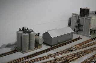
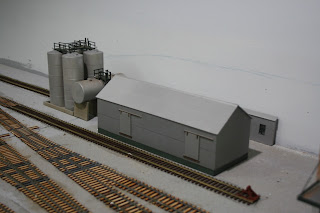
A couple of industries were identified throughout the long design and construction phases for this layout—a couple of decades now.  Nabisco had a bakery warehouse closer to the depot, but I could not fit it in there.  Still, I wanted Nabisco on this layout.  The photo above shows a Walthers “Magic Pan Bakeries” kit box (933-2915) just poking into the right side of the photo.  That is where something using those kit pieces will eventually emerge.  In the middle of the photo and industrial siding are sides from the Walthers “R.J. Frost Ice and Storage” kit (933-3020) that will become Eugene Freeze.  I have always liked this kit structure.  It fits well in many areas of the country, including here in Oregon.  Ordinarily, I resist using stock Walthers structures.  They appear on many, many layouts.  I hope I can modify these enough to at least show they are not stock, out of the box.


Another industry that commended itself to me is the partially-assembled Campbell plastics manufacturer—the olive-green structure in the photo.  I started building this kit many years ago.  Campbell designed this structure as a lift-slab (sides) building with a bow roof.  This is very common mid-century industrial architecture on the West Coast, so it fits well here. Little did I realize when I started this kit and picked a color scheme that the green would fit well in Eugene.  The University of Oregon (boo-hiss—I am an OSU Beaver!) colors are green and gold, so a lot of structures around Eugene pick up on that.  Maybe this is a plant making little rubber duckies!  <wink>


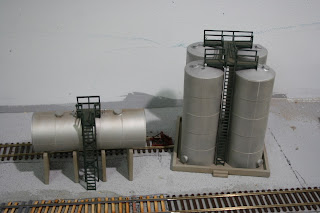
With three of the six sidings determined by both Eugene industry research and existing structure kits, the other three need something different.  From days gone by, I recalled a “petroleum row” north of the Eugene downtown.  Those bulk oil dealers are no longer there, replacing railroad service with pipelines and trucks.  Still, bulk oil dealers were a staple of railroading for much of the Twentieth Century.  With the bulk oil dealers no longer showing on SP (SPINS) track charts of 1977, I needed to look elsewhere.  I conferred with one of my regular crew members living in Eugene, a retired SP engineer.  He and his wife confirmed my memories and suggested a couple of dealer names and oil brands.  I subsequently found a Eugene City Planning Department historic document that added to my understanding of this now-absent industry.  One of the spurs will serve two or three dealers, just as they did back when they were rail served.


Another industry was identified when I consulted my model railroad “brain trust.”  I posed a question to several fellow modelers, particularly the few with strongly prototype-based layouts.  One came back to me with an excellent suggestion—survey my freight car fleet to identify if any car type had under-represented industry on my railroad.  That quickly led to my identification of mill gondolas as that under-used car type.  At least one steel fabricator was identified and another is either a fabricator or scrap yard feeding steel scrap to a steel mill near Portland.  I will place a steel fabricator on the spur at the RR-East end of the industrial siding, tightly alongside the wall.  


The final industry spot floated around in my head for a while.  I had a number of possibilities, including another bulk oil dealer spur or perhaps one of the many wood products mills in town.  I decided I did not need to add still more oil dealers, letting the single spur with two or three dealers suffice.  I disposed of the wood products mills as they consume a lot of space and I already have three large mills represented on my railroad.  Looking at the SPINS track charts again, I spotted the Bi-Mart warehouse.  Bi-Mart is an Oregon-based retailer much like Costco, but definitely local to Oregon. Home base is Eugene.  We frequently shop at Bi-Mart.  We have a funny story concerning our daughter’s “discovery” of Bi-Mart during her Freshman year at OSU.  Parents can’t tell a teen anything!  Bi-Mart has earned its way onto this railroad!


While I was settling the industries, I still needed to fabricate the turnouts and build the industrial spur.  I use FastTracks tooling for my turnouts.  This time, instead of confining the rails to that needed to fill out a FastTracks switch tie block, I chose to extend the rails on both ends.  I have noted with more recent turnout installations that I get better results with a bit more rail extending from the turnout, particularly on the point end.  This time, I chose to extend the rails enough that I could join them together and not need any additional track to complete the industrial siding.


I had some FastTracks flex ties from a prior project, but I needed more ties for this project.  Instead of the flex ties, I selected both fixed (straight) and flexible “Quick Sticks” tie blocks.  These have groups of five ties separated by spaces to insert and use a pc-board tie to maintain rail gauge.  This took some assembly planning on my part.  I needed to glue the rails to the ties, just like the switch blocks, but then cut out the connecting web to allow insertion of the pc-board ties.  I also needed to account for the gentle curve needed between a pair of the turnouts—an area using the flexible “Quick Sticks.”  


Underside of track sections extended from the switch tie block using “Quick Sticks” ties.  The upper track has had the gap webbing removed and the underside of the rail cleared of paint to allow insertion and soldering of a pc-board tie.  The lower track still has the webs in place.


I formed the curved track section in place, gluing it and fixing it with a hot soldering iron (heats and vulcanizes the Pliobond adhesive).  I used both three-point track gauges and “RibbonRail” curve fixtures to assist this process.  Once that set, I removed the turnout and track and removed the blank space webbing.


Once all the turnouts and extended tracks were mounted on their ties, I needed to mount them on the cork roadbed.  This was done with adhesive caulk, as with the rest of my railroad.  I marked all the gaps for pc-board ties and made sure the caulk was not present in those areas as I spread it elsewhere to fix the ties to the roadbed.  I chose to mount turnouts one, three, and five first, and then follow up with the other two, fitting them to the already installed turnouts.  


Initial dabs of caulk adhesive laid before spreading in place and then mounting the turnout and extended tracks.


The track is now installed for this industrial siding, although I do need to install the pc-board ties.  I move next to installing switch machines, controls, and track wiring.  I also need to install the rest of the spurs, for which I will use regular flex track.  I also can begin fabricating the industrial structures for this busy section of railroad.

Sunday, August 1, 2021

THE RAILROAD AT YEAR NINE

August 1 marks the anniversary of the start of construction on my SP Cascade Line.  Each year I conduct a photo survey of the railroad to document progress.  Last year’s survey may be viewed at:  https://espeecascades.blogspot.com/2020/08/the-railroad-at-year-eight.html  You can work back from that post through preceding years.  


While the past year has seen challenges, a major track project finally extended the WP Siding from in front of the Eugene Depot to fully one side of the reverse loop staging and arrival-departure yard.  This project was suggested originally by retired SP railroaders Tom Dill and Rick Kang at the first full operating session in June 2015.  You will see in this year’s photos that project required five double slip switches.  That completely explains the delay in accomplishing this track rearrangement.  Double slip switches are not something one should add to a model railroad lightly.  


Noting the genesis of that track project also brings a sad moment, as I reflect upon the loss of two of my core crew and the health challenges faced by others.  We lost Chuck Clark to heart issues at the beginning of lockdowns in March 2020.  Chuck was the foundation stone of our mid-Willamette Valley operating group.  This past spring, we lost Tom Dill to cancer.  My blog post on Tom attempted to convey his impact:  https://espeecascades.blogspot.com/2021/04/tom-dill.html  Still with us, but facing severe health challenges is Rick Kang.  Rick contributed mightily to the operating scheme on my railroad.  He has educated a great many of us on SP operating practices and the art and practice of railroad dispatching.  Each of these men and others have had a huge impact on my model railroad experience and I greatly miss their presence in my basement during operating sessions.


The railroad continues to roll and see enhancements.  Follow along as Amtrak Number 11, the southbound Coast Starlight, makes its way over my railroad.


AMTRAK No. 11 exits staging track #1 (representing traffic from Portland) and pulls over the first double slip switch that helps form two main tracks between the staging yard and the Eugene Depot.


The full scope of the track rearrangement at East Eugene.  Five double slip switches were required to establish a second main track while maintaining full access to Eugene Depot tracks and a developing industrial siding—seen here with switch tie plates placed in their future locations.


Befitting its status on the railroad, No. 11 has taken the main track at the Eugene Depot.  Typical of the SP, the main track is displaced one or more tracks over from the depot.  In the case of Eugene, the track closest to the depot is the “WP Siding” (reference is to the company name used to construct the Coos Bay Branch).  As seen in the previous photo, both the main and the WP siding now extend fully to the departure side of the arrival-departure yard.  Also notable in this view is the Eugene freight station, completed during the past year and a half.


As AMTRAK No. 11 rolls out of Eugene, it passes the Crown Zellerbach warehouse and the Eugene Planing Mill.


No. 11 crosses the Willamette River and into Springfield, passing the former Borden Chemical plant along the river.


At Springfield, No. 11 passes the under-construction Springfield Depot.  The depot kit is of an SP Type 18 depot produced by the Southern Pacific Historical and Technical Society.  We also get a view of the industry developing in Springfield.


No. 11 passes alongside sheds that are part of the extensive Rosboro Lumber Company facility in Springfield.


Rounding the curve at the end of the Springfield peninsula, No. 11 rolls by industry on the Marcola Branch.  The Neste Resins wood chemicals plant continues development.


No. 11 passes the former Western Lumber mill at Westfir and then crosses the North Fork of the Willamette River before plunging into Tunnel 22 and into Oakridge.


At the RR-East end of Oakridge, No. 11 takes the main and passes another RR-West freight waiting for it in the Oakridge Yard.  The freight has its mid-train helpers entrained and is ready to follow AMTRAK up into the mountains.


No. 11 continues to roll through Oakridge.  Both a through freight and the Oakridge Turn (local freight) await AMTRAK’s passage.  One of the tasks of this past year was to paint much of the exposed track on the railroad.


No. 11 passes under Montieth (aka, Rooster) Rock.


No. 11 crosses Eagle Creek on its way out of McCredie Springs.


Halfway up the Cascades climb, No. 11 rolls through Wicopee and out over Salt Creek Trestle.


No. 11 crosses Noisy Creek Trestle and passes through Tunnel 9 on its way into Cruzatte.  Wicopee is down below, on the right.  


No. 11 passes the company village at Cruzatte.


Just beyond Cruzatte, No. 11 crosses over Shady Creek Trestle, the third major steel viaduct on the line.


No. 11 completes the climb to Cascade Summit after passing through Tunnel 3, the Summit Tunnel.


At the other end of Cascade Summit, No. 11 rolls by the wye with its unique single-ended tunnel for the tail track.


Our journey is complete as AMTRAK No. 11 takes it habitual spot on the outside track of the Crescent Lake staging loop.


The big effort this past year involved completing the second main track at RR-East Eugene.  Four of the five double slip switches were installed and wired to a new control panel this past year.  The railroad has been brought back to life—carefully—after the shutdowns of the previous year and a half. 

Sunday, June 27, 2021

Model Generations—SD45s

 Model Generations—SD45s


My presentation on “So You Want to Build a Dream Model Railroad?  --One Man’s Journey” will be part of the NMRA National Convention to be conducted virtually, July 6-10.  “NMRA 2021 Rails By the Bay is hosted by my many good friends from my days working in that South SF Bay Area—for me at Moffett Field in Mountain View and Sunnyvale. They have a great program of clinics and other material, all aimed at the on-line format we have all become accustomed to over the past two years.  One can partake of this convention from the comfort of home for a modest registration fee.  Check it out at the official convention website:


http://www.pcrnmra.org/NMRA2021/


During the buildup to this convention, all presentations were pre-recorded.  This should minimize technical difficulties at the time of presentation, something most of us have experienced sometime over the past couple of years.  My recording session placed me in contact with Heath Hurwitz, who also runs a model railroad modeling podcast.  Talking with Heath and introducing myself, I realized I had a wealth of experience with prototype modeling not directly covered in my presentation.  Indeed, readers of this blog will likely get the impression I am a layout builder, but not necessarily catch that I spent decades before this layout tightly focused on building ever more accurate and detailed railroad models, notably locomotives and rolling stock.  


Many of my Bay Area friends know this.  They saw it develop over the years, but more recent acquaintances likely will only know me as that guy building a large operating layout focused on the SP in Oregon.  With that in mind, Heath encouraged me to dust off some of my older models as a springboard for talking about how one develops as a modeler and makes choices along the way.


Three generations of SP SD45 modeling.  


The photo above shows three generations of my SD45 modeling.  8895 in the rear is an Athearn “blue box” model, ca, 1973, detailed and painted before diesel detail firms like Detail Associates or Details West came on the market.  8924 in the middle is a Kato model detailed in the 1990s.  Scale hood width and “modern” details contribute to a decent layout model.  7474 in front is a relatively current Athearn RTR loco of the past few years.  Athearn has done all the work I formerly spent hours on, allowing me to simply change the coupler, add a decoder coded with the unit number, and place in service.  This allows me to concentrate on building and enhancing the layout.  That has become my reality over the past decade of layout construction, although I still hope to get back to my modeling roots as the layout matures.


As I dug around in my storage containers searching for these illustrations of modeling efforts, I ran across several project bins with the base models, detail parts, and photos that I hope to use to create models in the Twenty-First Century.  My models today start from a photo.  The freight house in the background of the photo began from pieces of only two or three photos, but I could fill in the rest of what I needed using my library full of reference materials, acquired over the past half century.  


The bin of SD45 parts and photos represents a different tact.  I have a stack of my own photos, augmented by photos (often shot by fellow railfan friends) captured off the internet.  Add to that  the detail parts.  I had the good fortune to meet and know Gordon Cannon who made exquisite detail parts for EMD locomotive models.  After Gordon passed, his part line was purchased by Dave Hussey and is still available:  http://www.cannonandco.net/.  At the very least a good Cannon cab and nose sets a model apart.  


I am grateful for the efforts of model manufacturers and detail parts makers that permit ever more detailed models.  Equally important today as I juggle where to focus my time and effort, are the many fine highly detailed prototype-specific models now available straight from the box.  Such “check-book modeling” has allowed me to build and operate a large model railroad while still enjoying finely detailed equipment rolling by.  Still, the urge to go to the modeling bench to sit down with a model, parts, and tools to create something unique flows through my veins.