Sunday, February 24, 2013

SPRINGFIELD TRACK AND ROADBED - 2


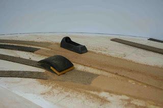
Track and roadbed at Springfield have been permanently affixed.  With track centerlines marked, the cork roadbed was glued in place. http://espeecascades.blogspot.com/2013/01/springfield-track-and-roadbed-1.html  The sheet cork pads for the three major switch complexes (ends and the mid-town cross-overs) were faired to the heights of connecting standard cork roadbed.  This was accomplished with a Stanley Surform™ and 60-grit sandpaper.  The rest of the roadbed was sanded for uniformity.


Height fairing of cork sheet.

Rail (code 83 to code 70) and tie height transitions (Fast Tracks to Micro Engineering) were accounted for with cardstock glued to the roadbed where the transitions occur. 


Tie height transitions formed by cardstock.

Throwbar slots were created by first drilling a ¼” hole at the center and then expanding with a router bit.  I got a little “enthusiastic” with the router as I learned to handle it, so I needed to go back with some wood filler.  It’s an imperfect job, but I’d rather err on the side of free function of the throwbars.  I also had to drill holes for the frog wire feeders to the Micro Engineering turnout frogs.


Throwbar slot routing.

Another item that needed to be accounted for before laying track was creating holes and hatches for Kadee uncoupling magnets that will be mounted on hinged flaps.  Three of these are located on tracks well away from the aisle edge –locations difficult to reach for “manual” uncoupling.  I’ll describe my uncoupling magnet mounts in a subsequent post, once I complete the installations.


Roadbed hole for uncoupling magnet.

The final bit of roadbed preparation was a coat of paint.  This both seals the cork to slow its natural drying out over the years (I hope!) and provides a good basic gray color.

With the roadbed prepared, the track could be laid permanently.  Prior to attaching the track, I relaid the track to be sure everything fit where I expected it to fit.  I also took the opportunity to join groups of turnouts into continuous assemblies by soldering their rail joiners together.  I also joined two or three sections of flex track in the same way.  This ensures critical alignment for these groups and made handling them easier during the track-laying process.

I used Dap 230 caulk in both aluminum-gray and clear varieties to affix the track.  I laid a bead of caulk over a “fair stretch of track--often a run of multiple sections of flex track or a turnout assembly.  The caulk bead was spread (like butter) with a putty knife.  The track was then placed in position.  Track sections were joined and then final alignment set using several RibbonRail curve tools and the “Mark 1” eyeball.  The caulk provides decent working time, but also sets quick enough to allow work on multiple tracks without disturbing prior track laying. 


Track and roadbed permanently laid at Springfield.


RR-West end of Springfield and Marcola Branch track viewed from Westfir.

Now that the track is down, the wiring and switch machine installation begins!
Saturday, February 16, 2013

MY MICRO ENGINEERING TURNOUT FAILURE


This is a tale of great expectations gone awry.  Whether it is due to my own incompetence, materials used or available to me, or a fundamental material composition flaw, I will leave to the reader.  My point to this sorry tale is to provide a warning to fully investigate and satisfy yourself that all steps necessary to use a product are satisfactory prior to quantity purchase.

My original trackwork plan for the HO scale SP Cascade Line was to use Fast Tracks turnouts throughout.  As I approached full-size planning a year ago, I purchased sample Micro Engineering # 6 and Walthers Shinohara #8 turnouts to assist with planning.  Recalling the NMRA conformance testing of HO scale turnouts a couple of years ago, I knew the ME turnout was pretty close to standard, though a minor flaw prevented an NMRA conformance warrant.  I was sufficiently impressed by the mechanical design of the ME turnout, that I altered my plan to use the ME turnouts where #6 size were needed, but still using Fast Tracks #8 turnouts for the longer (mostly mainline) locations.

Preparatory to final installation of track in Springfield, I have been attempting to solder frog wires to the underside of the ME frog casting.  ME provides a “button” on the underside of the frog for this purpose.  The idea is to solder a wire onto this underside button and then feed it through a hole in the roadbed for the electrical connections needed for a “hot” frog (frog polarity switches with point movement). 


Frog button on underside of Micro Engineering turnout.

I have had extreme difficulty making that frog wire solder joint.  The frog casting metallurgy reacts quite differently than nickel silver rail.  It is very hard (difficult to drill into) and does not take solder easily.  I have tried several methods for attaching the frog wires.  Each begins with a very clean button.  I have used both a fiberglass brush and a brass wire brush to clean the button.  My 35 watt electronics soldering iron could not achieve a solder joint at all.  I have used a resistance soldering unit to apply very localized high heat.  I have used both the soldering unit tweezers and the alternative ground clip and probe.  I have tried various unit settings, including very high. 

For solder joint geometry, I have tried direct soldering wherein I flatten the frog wire by crimping, bend the wire to a 90 degree angle, and hold it on the frog button.  Both button and wire have rosin flux applied.   Using the solder unit ground clip on the top of the frog, I apply heat with the probe to both button and wire.  Initial attempts achieved only cold solder joints, easily broken.  Raising the heat level simply led to melted—and often burning (!) ties!   Clearly, I was using too much heat!

Melted ties near frog on Micro Engineering turnout.

I moved on to drilling a hole to feed the wire into, reducing mechanical stresses, while providing more surface for the solder to make a joint.  This, too, resulted in melting and burning ties.

I achieved a successful solder joint on only about half of my first dozen attempts.  I destroyed three (and counting!) turnouts along the way to making a dozen “successful” joints.  This is absolutely unacceptable. 

I finally did make contact with Micro Engineering.  They were unable to duplicate my symptoms.   They used a large soldering iron so apparently had sufficient quick heat.

I finally developed a successful technique involving drilling a hole, quickly getting the frog onto my vise to relieve any heat build-up.  I then add the resistance solder unit ground clip on the top of the frog, resting the turnout and clip assembly upside down spanning the jaws of my vise.  Flux and the frog wire are inserted, the probe positioned and then heat applied while feeding solder (standard electrical 60/40 rosin core).  The addition of the vise seems to have largely relieved the heat buildups, while the resistance solder unit is able to apply sufficient localized heat to achieve a satisfactory solder joint.  Though I found a technique to keep from destroying still more turnouts, I am not satisfied with the steps using tools and fixtures away from the layout location.

I am shifting back to my original plan to use Fast Tracks jig-built turnouts throughout.  I will attempt to salvage what I can of my current ME turnouts, but will buy no more, indeed, cancelling a large order. 

I am disappointed and frustrated.  Railroad construction will grind to a halt until the Fast Tracks jigs and fixtures arrive.

Caveat Emptor!