Pages

Sunday, December 29, 2013

A DEPOT FOR EUGENE


As I work toward initial operations on the current railroad—the “Valley Core"—I find myself diverting into several “side” projects.  Such is the case of the depot construction for Eugene.  It is not needed directly for operations, but it provides important context for the tracks currently in place at Eugene.  As I show the layout off to family and friends through the holiday period, I find the depot would be useful for them to relate to the railroad.  Finally, I needed a different project to lift me out of a bit of a holiday funk.


Eugene depot model in position on the layout.

My current Eugene depot uses the Walthers “City Station” kit (933-2904).  This is intended as a long-term stand-in until I finally get around to scratch building a more accurate depot.  The Walthers structure is the right size and captures the look of the stone and brick depots along the original Oregon and California (later Siskiyou) Line.  These include Medford, Grants Pass, Roseburg, Eugene and Albany.  In addition to published photos, I consulted photos on Joel Ashcroft’s site: http://spcascades.railfan.net/photosEugene.html  and ordered a set of depot photo prints from the Shasta Division archives from “Photo Bob” Morris: http://www.snowcrest.net/photobob/index.html  Out of respect for the intellectual property rights of both sites and the excellent (commercial) resource provided by Bob Morris, I provide just links and let the reader judge whether my use of this kit is a suitable stand-in. 

Assembly of the depot is relatively straight forward, though I will note several things I did to mine.  First, this is a brick structure.  That meant painting the brick siding an appropriate base color (I used PolyScale Boxcar Red), adding individual brick highlights with Primsacolor pencils, and applying a mortar treatment.  I began with a thin gray wash (1:3 gray paint:water plus several drops of Liquitex Flow Aid).  Though this altered the basic brick color a bit, I did not get the desired mortar line contrast.  A second application of the gray wash was a little better, but still not much contrast.  A fellow modeler suggested I go all the way with a white mortar wash.  This proved to be the solution.  Though the actual mortar on the Eugene depot is gray, one uses white in the model form to compensate for the small scale—the art of model railroading!

For the window sashes, doors and trim colors, I consulted the Steam Age Equipment Company SP Common Standard Plan books.  Volume 1 lists paint colors for company buildings.  By 1956 (the revision date on the plan sheet), masonry structures used either gray or tan trim.  The photos I looked at showed the trim color had shifted from darker (bottle green was a previous trim color) to lighter—gray or tan.  I selected gray based on the darker brick color and looking at the few color pictures I could find of similar structures along the Cascade and Siskiyou Lines.  I stand prepared to receive an alternative view—inevitable once one makes such a choice.  I’ll take such comments under advisement when I finally tackle a more accurate depot model.  Although the standard plans call for white window sashes, I have no indication of them at Eugene nor on the similar structure photos I looked at, so windows, doors and trim all received a light gray color.  The roof was painted SP’s Moss Green (PolyScale Depot Olive). 

I installed basic wall partitions between the central operator bay and the waiting rooms on either side.  I also installed a floor.  I chose not to light the structure, as I do not intend conducting night or low light operations on the layout.  No further interior detailing was installed as the structure will be placed two feet away from the aisle.  It will serve as a good stand-in.


Saturday, December 7, 2013

PREPARING FREIGHT CARS – FMS DECKS


After the push to complete the current mainline with the Willamette River bridge between Eugene and Springfield, I was in need of a break, or at least a change of pace.  One of the wonderful things about the model railroad hobby is that it has so many facets that one can usually find a project to fit one’s “mood.”  While recovering from the Thanksgiving holiday, I needed a shift.  My focus turned to the shipping and storage boxes containing the hoard of rolling stock acquired for my dream layout.  Initial operations on that dream layout are fast approaching, so it was time to start preparing some of that equipment for operation. 

I have chosen to focus on the early 1980’s for the initial set of equipment on the railroad.  This has to do with the relative ease of equipping the motive power fleet with decoders, availability of sufficient suitable cabooses, and adequate model coverage of required freight cars.  Indeed, I have several storage bins full of SP and other freight cars for this era, largely ready to go.  More cars are needed, though, especially those used to ship forest products.

As I began pulling out boxes of freight cars, I came upon my recent acquisition of SP bulkhead flat cars.  The 1962 and 1956 bulkhead designs were released recently by the Southern Pacific Historical and Technical Society model program: https://espeemodels.com/cgi-bin/commerce.cgi?display=home
For me, the 1962 design bulkhead was the “definitive” design applied to the major postwar classes of F-70-6 and F-70-7 riveted flat cars.  I have a number of photos of these shot in the late 1970’s and early 1980’s, still carrying lumber for the SP.  Though the SP lists the bulkheads as being for plasterboard service, many found their way into lumber service.  SP designates them by AAR code “FMS,” meaning a general flat car with special loading devices applied—the bulkheads.

An “issue” with the SP Models release is that all of the car body, including the deck and bulkhead timber, has been painted SP mineral red.  This is a reasonable choice for the model program, but a conscientious modeler needs to complete the job of representing timber decks and bulkhead lining.  SP did not paint or treat the deck timbers.  Pictures show the timber weathering to a dark gray tone. 

I replicated this with a fairly standard technique for representing weathered wood.  I used PolyScale acrylic hobby paints.  Although Testors parent corporation has discontinued the PolyScale line, similar acrylic colors are now available from other sources.  Micro-Mark’s new line of MicroLux paints fills this important gap.  First, a gray base coat of paint was applied.  I used “aged concrete” as a good light gray with a yellow cast, picking up a couple of color features of weathered timber.  I applied this with a ¼ inch brush, brushing in line with the boards.  I was careful but not fastidious about paint application.  Over-swipes could be cleaned up later with touch-up paint.  Streaks in the gray were desirable for providing color intensity variations among individual boards.  After this paint set, I applied a color wash of “rail tie brown” thinned 1:2 with alcohol.  The deck coloring was completed by a wash of “grimy black,” thinned at 1:2 with alcohol.  It is important that the last color wash be the darkest color (grimy black) as this settles into the crevices to provide surface definition.  Once all of this set, I returned with touch-up paint, using “DRGW Freight Car Brown” as a decent match to the mineral red applied to the cars.  One touch-up item comprised the bolster straps on the deck, which inevitably got covered by the three deck color applications. 


Stages of timber deck finishing on SP bulkhead flat cars.  Top pair are as-delivered models.  Next pair of cars have “aged concrete” paint applied.  Third pair of cars has a wash of “rail tie brown” applied.  Final pair of cars in the foreground have received the final wash of “grimy black” and touch up of the car body mineral red.  The ¼ inch brush for deck paint and micro-brush for touch-up paint are in the near foreground.

I still need to apply Automatic Car Identification (ACI) labels to the cars, as SP was a leader in that technology.  ACI was first required on the national car fleet in 1967, though the SP began the program earlier.  I also need to paint the trucks mineral red, the SP standard for these cars, and then weather all the “steel.”  For now, I have a great start with weathered decks and bulkheads.

Saturday, November 23, 2013

BRIDGING THE GAP – 2


Completion of the Willamette River Bridge between Eugene and Springfield has been accomplished.  The gap is closed!


First train over the Willamette River Bridge!  SP X7474 East crosses the river toward Eugene.

The previous post (http://espeecascades.blogspot.com/2013/11/bridging-gap-willamette-river-bridges-1.html) discussed the steel bridge sections (two Walthers single track through trusses and a Micro Engineering deck plate girder) and the concrete pier fabrication.  Completing the job required a ballasted deck pile trestle for the Springfield approach.  I built a trestle bent jig using SP CS1600 plans found in the Steam Age Equipment Company publication of Southern Pacific Lines Common Standard Plans, Volume 1.  This matches well to my photos taken at Springfield in April, 2013.


Trestle bents built using SP Common Standard plans.


Springfield pile trestle approach, April, 2013.

My model trestle was fabricated using Evergreen styrene strip and a bit of V-groove siding for the ballast deck.  N-scale cork roadbed continues the model ballast form from the “land” side.


Model ballasted deck trestle trial fit.


Completed pile trestle approach with track loosely placed.

With all elements of the bridge fabricated and installable, I decided to try painting the Willamette River.  This was my first artistic venture using acrylic paints.  It took a couple of tries, but the I finally got the desired effect of sky and river bank tree colors reflected in the “water.”  While I was at it, I experimented with some backdrop painting, continuing the river onto the nearby backdrop.  The top photo of this blog post shows the result.  My attempts at weathering the bridge and pier pieces took several attempts using acrylics, Bragdon weathering powders and a final overspray with the base colors. 

A quick wiring job for the now-complete Eugene West Main detection block completed the job.  The bridges and bridge track are lightly affixed with Dap 230 adhesive caulk.  This will allow me to remove these pieces for further scenery work.  Eventually, the two bridge track sections will need feeder wires, but that can be done only when the installation is deemed complete and permanent.  For now, I’ll have to accept power fed through the rail joiners.

With the Willamette River gap closed at last, I can run from one end of the current mainline to the other—RR-West Oakridge to the RR-East end of the Eugene depot trackage. The elusive goal of beginning “beta test” operations on the current railroad just drew much closer.


Willamette River and bridge, April, 2013. 

Note that the actual Eugene truss bridge span is a long curved-chord truss while the Springfield truss span is a pin-connected truss.  I did not have space for both bridges, so I elected to do what a railroad engineer would do—use two standard bridges of the same design.  That led to the Walthers single track through truss which has the right “heft” needed for a heavy mainline.

Monday, November 11, 2013

BRIDGING THE GAP: WILLAMETTE RIVER BRIDGES – 1


An overdue project entails closing the track gap between Springfield and Eugene.  Although the primary structures, a pair of Walthers single track through truss bridges (933-3185), have long been built, I needed to build most other parts of the scene. 

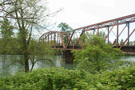
Bridge piers were high on the list.  The prototype piers are fairly simple concrete shapes.  The standard SP 12:1 batter (downward slope) and 45-degree cutwater ends can be seen in the prototype photo taken last Spring.


Willamette River Bridge from Springfield, April 2013. 

I considered various ways of replicating these piers.  No commercial castings satisfied the need.  I settled on cutting them out of wood blocks using my table saw and compound miter saw.  After a trial run using a fir 2x4, I settled on using poplar as the wood.  This is a close-grained wood readily available in local home centers.  A six-feet long 1x4 plank became three pieces laminated to provide a 2-feet long 2.25 inch thick block.  The overall height and long dimension batter was cut with the table saw.  A 12:1 batter works out to about 5 degrees angle, easily set on both saws.  The compound miter saw was set for the 5 degree batter and 45 degree cutwater ends (using both saw angles available).  Lots of careful setup and clamping were necessary!


Progressive formation of bridge piers.  Fir 2x4 trial pieces are on the left.  Laminated poplar block with 12:1 batter from table saw is next.  Completed bridge pier is on the right.

The poplar piers were filled and sanded.  Multiple coats of “rattle can” Rustoleum gray primer were used to seal the wood and provide a base color coat.  I am undecided as to whether I will use this base color or go with a bit lighter gray shade provided by hobby paint “concrete” colors.  The prototype photo shows lots of dark gray splotches, typical of weathered concrete here in Western Oregon.

Moving on to the Eugene side approach, I am using a single Micro Engineering 50-feet deck girder span.  The prototype bridge uses a steel trestle affair, but I needed to compromise to a single girder span given the available space.  Note those same space considerations led to the use of the Walthers through truss bridges rather than one pin-connected truss (similar to the Central Valley truss, 21—1902) and much longer curved chord truss of the Eugene span. 

A “concrete” bridge abutment was built using styrene.  I am very familiar with fabricating styrene parts so this seemed the best way to capture the desired shape.  The resulting abutment features a pocket at the top for the girder to rest within.  This gives way to the standard SP 12:1 batter sloping down.  I’ll add wing walls later as the scene develops.  The abutment is fabricated for mounting to the underside of the plywood subroadbed.  All of the bridge parts will remain removable until the river scenery is formed and the river painted. 


Front of Eugene bridge abutment.


Underside of Eugene bridge abutment.

In addition to painting the concrete parts, I also needed to paint the steel bridges.  I ultimately had to unpack my airbrush and hook up the compressor.  These highly useful modeling tools have languished in packing from moving FAR too long!  With the abutment fabricated and mounted and the piers placed, the Willamette River bridge structures are coming together.


Willamette River Bridges in process.

I’ve chosen to mount the bridge track directly to the “steel” bridges, making them “open deck.”  The prototype through trusses are open, but the approach spans are ballasted decks.  The Micro Engineering deck girder matches the height of the Walthers through trusses.  There is not enough clearance on the through trusses to add a ballasted deck, so I chose to keep both them and the approach span open. 

Bridge track is one of the next steps.  I am using Micro Engineering bridge track.  I began by painting the track an overall gray-brown.  Historically, my first choice would have been to use a “rattle” spray can of Floquil Rail Tie Brown.  Unfortunately, Rutstoleum-Testors discontinuance of the Floquil paint line this year eliminated that option.  Instead, I used a combination of a pair of Rustoleum (ironically!) spray cans: Espresso and gray primer.  I sprayed the brown first and quickly followed with a light misting of the dark gray primer.  The mottled effect provides a good base for further paint detail.  Detail was supplied using Floquil paint pens (which I could still obtain), using roof brown and weathered black on several ties.  A Woodland Scenics “steel” paint pen was used on the side of the rails.  The overall effect looks quite good to my eyes.


Painted and “weathered” bridge track.

Still to come is the pile trestle approach on the Springfield side as seen in the prototype photo above.  Having fabricated the bents from styrene, I discovered I had not obtained the right size of strip for the trestle stringers.  An urgent trek into Portland for the larger hobby shops there provided the necessary materials.  I hope to report on completion of the track over the river next time.

Friday, October 25, 2013

OAKRIDGE SWITCH LINKS


Completing the manual switch links for the current railroad, I moved on to Oakridge.  As shown for Eugene (http://espeecascades.blogspot.com/2013/09/eugene-manual-switch-linkages-installed_29.html), fascia was installed, knob holes bored, backer plates installed and threaded rod installed for the switch links. 


Fascia and manual switch link knobs at RR-West Oakridge.


Manual switch link knobs in fascia at RR-East Oakridge.  Note knobs for switches at the wye tail are mounted directly to the layout structure—no fascia.

The pair of switches at the tail of the Oakridge wye required a bit different linkage.  The roadbed support for the wye tail is quite narrow.  This presented the opportunity and need for a linkage that works from both sides.  This was accomplished by passing the threaded rod used for the linkages through both sides of the layout support, passing through a bracket mounted to the Blue Point switch machine.


Oakridge wye tail switch link.

While I was installing knobs for the Oakridge switch links, I took the opportunity to change several of the knobs at Eugene to provide color coding.  The basic knobs are black, but the switches along the back of the Eugene depot area (most of them off the “WP Siding" in front of the depot) now have blue knobs.  Similarly, the RIP track and scale track switches now have red knobs.   The color coding helps differentiate these switches from the bulk of the yard switches.


Eugene color-coded switch link knobs.

A Note on Blogging

Finally, a theme I find in common lately on several blogs I follow concerns the need for focus during layout construction, particularly for larger projects.  A blog can be a great way to force that focus to accomplish something tangible within a given period. 

A blog can serve as a public project progress report—something I was quite familiar with in my NASA career.  I so appreciated other model railroaders’ blogs, that I resolved I would begin my own blog when I began construction of the dream layout.  I originally anticipated posting monthly, but found I could achieve a bi-weekly post, a pace I have maintained since construction began in August, 2012.

“Feeding” this blog has forced me to focus on several occasions, just to have something tangible to report.  As one fellow blogger notes, it is easy to get diverted into a variety of different tasks on a large project (layout), with none of them directly showing progress in a given period.  Those tasks are all necessary to the larger picture, but it remains important to keep making tangible progress, as well. 

There will be occasions when one blog post looks a lot like some previous post.  Such might be the case with this current post on Oakridge switch linkages and the one a month ago on Eugene switch linkages.  Both report progress.  Each shows a slightly different aspect of the same overall task.  Repetition is in the nature of the task –it is needed for each station along the railroad.  Still, it does show how long it takes to work through the major building blocks of this project.  It was that sort of information I found so useful while planning this railroad to determine what was feasible.  I appreciated others posting on their efforts.  I hope I am returning the favor to other model railroaders contemplating layout construction.

Saturday, October 12, 2013

SPH&TS CONVENTION-2013-FRESNO


The Southern Pacific Historical and Technical Society (SPH&TS: http://sphts.org/) held its annual convention in Fresno, CA, this year.  This has been a major annual event for my railroad hobby for over two decades now.  I sat on the fence about attending this one (What’s in Fresno? –grin), but ultimately decided it was the people connections at this event that now draw me to it.  I am glad I chose to attend!  Convention Chair Chuck Harmon and his crew put on a fine event with informative clinic presentations, an interesting railroad trek in the area (more below), and “the usual” convention activities. 

The convention began with a trip out to the Hillcrest & Wahtoke 15” gauge railroad in Reedly, CA.  (http://hillcrestreedley.com/)  Over a mile of 15” gauge track winding through the remnants of a Christmas tree farm serves as the venue for this steam railroad.  Owners Sean and Melissa Bautista have built upon their railroad interest to provide a great local attraction and the shop to support it.  That shop now provides support to other large “ride-on/in” railroads, including a major entertainment and theme park empire.  Melissa was ever the gracious and informative hostess, making this a happy surprise for the convention.


Hillcrest & Wahtoke Railroad, Reedly, CA.

A fine set of clinics were presented on Thursday, Friday and Saturday.  Highlights for me included Mike Bording describing his initial duties as an Assistant Trainmaster at SP’s Fresno Yard, Joe Dale Morris providing a trip description up the Friant (Clovis) Branch, Tony Thompson on PFE Operations, and Dick Harley on modeling PFE steel ice reefers.  Dick has inspired me with PFE modeling tips through the years and was one of the first to provide me a technique for analyzing a car fleet for the most significant car classes—the ones that “need” to be modeled first.  Rob Leachman presented a double-length clinic on the UP/SP/PFE Salad Bowl Express/Fresh From the West service of the 1970’s.  Rob was part of the UP team that analyzed the traffic and proposed a service solution to resist the shift of the valuable produce trade from train to truck.  Though my SP Cascade Line is focused on the forest products industry, I remain mindful of the significance of Pacific Fruit Express operations to the SP’s bottom line. 

I “stole” time Friday evening to take in a couple of local model railroad layouts.  The first was the Fresno O Scale Group, located in a light industry warehouse.  Hosted by John Ford, Dave Meyers and Jay Criswell, the group has created a great O-scale empire which they populated with mostly Southern Pacific equipment for our convention. 


Fresno O Scale Group Layout.


Sugar Beet train on the Fresno O Scale Group layout.

A pleasant surprise on this layout was a model of the Tilbury Cement reload that used to stand behind the Springfield, OR, depot.  I’ve been staring at the plans and modeling articles on this facility written by Harry Bonham in 1996 issues of “Railroad Model Craftsman.”  Ever since taking photos of the real facility in 1975, I’ve had an interest in modeling it.  It will appear in its rightful space in Springfield on my layout.


Tilbury Cement reload model by Overland Models on the Fresno O Scale Group layout.

Our second layout visit saw Boyd Cline’s HOn3 Rio Grande narrow gauge layout.  Common to many narrow gauge layouts, Boyd exhibited good modeling as he shoe-horned his layout into a typical bedroom.


Boyd Cline and layout.  <Sorry for the picture movement in low light.>

During the SPH&TS convention, I renewed friendships, made new friends, and made important contacts for future efforts on my SP Cascade Line.  I’m glad I made the trek to Fresno!  Next year’s convention returns to San Luis Obispo, CA.  We’re eager to attend!

Sunday, September 29, 2013

EUGENE MANUAL SWITCH LINKAGES INSTALLED


With wiring completed for the tracks and switch frogs in the Eugene depot and classification yard area, it was time to move on to the manual throw switch linkages.  I use Blue Point ™ switch machines for the manual (vs. powered) switch throws.  As previously discussed in a post on my Springfield station progress (http://espeecascades.blogspot.com/2013/07/switch-linkages.html), I developed a switch throw using threaded rod, cabinet knobs and a small screw eye for the connection to the Blue Point throw arm.  The knobs are semi-recessed into the fascia, so an important task was installation of the fascia for Eugene.


Fascia top backing plates being installed at Eugene.

The fascia begins with a top backing plate mounted to the yard plywood subroadbed.  I use pocket screws to attach the 5/8 inch plywood plates.  A similar height plywood strip is attached to the base of the hardboard fascia.  When assembled, almost the complete hardboard fascia front is backed by the 5/8 inch plywood.  I permanently attach the fascia hardboard front to the backing plates using Liquid Nails for Projects ™ and brads.


Fascia hardboard front being installed at Eugene.

An additional back plate is installed behind the fascia top backing plate in places where manual switch linkages or magnet hatch controls will be installed.  A center or rod clearance hole is then drilled through the complete assembly followed by removing the additional back plate.  A hole saw is used to bore the recess holes for switch knobs (2-1/2 inch) or magnet knobs (2 inch).  With the recess holes bored, the final back plate is re-installed prior to installing the switch link rods.


RR-West Eugene fascia with knob recess holes bored.

Several of the switches are mounted close to the layout edge.  I needed to fabricate a bracket to attached to the Blue Point throw bar to lower the actuating rod attachment.  This accounts for the height below the subroadbed needed to clear my 2-1/2 inch knob recess holes.  The brackets were formed from 0.031 inch thick brass with styrene stand-offs to account for the depth between the Blue Point throw bar and the side of the machine.


Offset bracket for Blue Point switch machine


Offset bracket mounted on Blue Point machine.


Fascia recess hole with offset bracket for Blue Point switch machine behind it.

In addition to the five switch machines needing a height offset bracket, one machine needed a bell crank to provide a clear run for the actuation threaded rod.  The addition of switches for the Car Shop (Repair In Place) tracks masked a switch machine for the yard lead.  A simple lever arm and bearing mount was fabricated from brass strip and tube.  Sorry, I have no photo of this mounting (lots of ugly wires in the immediate vicinity block a clear view). 

Thirty-eight switch links were installed for Eugene Depot and Classification yard.  Magnet flip hatch actuators are to come using model airplane choke/control link tubing.  In the meantime, I can better check the Eugene yard complex using aisle-mounted switch linkages.


Switch link knobs mounted in the Eugene fascia.

Sunday, September 15, 2013

EUGENE CLASSIFICATION YARD WIRED


Completing the wiring for tracks in the general area of my Eugene depot, the classification yard has been wired.  This included eight tracks, thirty switch machines, and seven power “blocks.”  All of the track in the classification yard is unsignaled, so all seven power “blocks” are connected to each other at the station panel under the layout.  Having seven distinct power “blocks” allows me to easily disconnect one for trouble shooting. 


Eugene Classification Yard.  The pair of GP9s to the left are on a depot “City Yard” track.  The GP9 in the distance is on the west switch lead and ladder.  Headlights are on, so the wiring has been successful!

I’ve been experimenting with structure locations and modifications to structures.  The industry buildings alongside the backdrop keep getting rearranged as I experiment with building heights and depths. 

Sharp eyes will spot the mock-up for the Eugene car shop shed near the water tower and switching GP9 in the photo.  As noted in a previous post (http://espeecascades.blogspot.com/2013/08/adding-to-eugene.html)  on modifications to my Eugene track plan, I provided tracks for the Repair in Place (RIP) facility.  I was inspired by photos and track plans for Eugene’s facilities up until the 1960’s.  Though my car shop shed is shorter than the prototype, it will serve for this model railroad.  

Saturday, August 31, 2013

EUGENE DEPOT WIRED


Most model railroads require as much time spent below the layout surface as above it.  Typically, the “fun stuff” is at the surface and above (track, trains, structures, scenery), but vital elements are underneath: wiring and switch machines.  With track for the Eugene depot and classification yard laid, the past few weeks have been spent in “the land down under.” 

Fifty-one switch machines—both Tortoise ™ power machines and Blue Point manual throws—were installed for the Eugene switches. 

Wiring is now underway with the depot tracks complete.  The depot tracks comprise a single power district connected through a PSX circuit breaker.  The depot tracks are divided into ten power blocks, with six of these blocks wired for potential detection.  Detected blocks require the block sub-bus to maintain separation between its two wires.  “Dark” (undetected) tracks have block sub-bus wires “gently” twisted.  Proof of successful wiring can be seen in the photo where the loco is lit and a DCC brakeman (made by former “DCC Lunch”-mate John Plocher) has a lit lantern. 


Eugene Depot tracks wired.  Depot tracks are the four furthest tracks in plus the industry spurs between the depot siding and the backdrop.

As I began to run the test loco on the depot tracks I had to trim the switch machine throw rod projecting through the throwbars.  I clipped the music wire rods close with a hard metal nipper and then trimmed them the rest of the way with a cutoff disk.  Therein lay a problem.  I recently replaced the Sears motor tool I used for five decades with a new two-speed Dremel.  The high speed for the cutoff disk produced too much heat in the rod for the surrounding plastic throwbars of a pair of commercial turnouts.  These were among the few remaining Micro Engineering turnouts I had in stock after my switch to Fast Tracks jig-built.  They are just visible on the left side of the photo of the depot tracks, in front of the brakeman.  The throw rod heated up by the cutoff disk melted right out of the throwbar.  This is a potential problem for any commercial turnout with a plastic throwbar.  I just encountered it following my change of motor tool (presumably with a higher speed). 


Original plastic switch throwbar has a melted out hole for the throw rod.

The melted out hole in the plastic throwbar necessitated a throwbar replacement.  I’ve had to do several of these for various reasons.  My experience with Fast Tracks jig-built turnouts means I have the skills, tools and materials to do such replacements quickly and easily.  Two new printed circuit (pc) board ties got insulating notches filed in them.  The original plastic throwbars were removed and the new pc-board ties inserted.  The switch points were then soldered to the new throwbars.  The switch machines were remounted with new throw rods (A longer throw rod is needed to aid the installation process.).  The new rods were trimmed and I now have two fully functional switches.


Turnout with replacement printed circuit board throwbar installed.

Monday, August 19, 2013

ADDING TO EUGENE


As I build the SP Cascade Line, I find the layout “speaking to me” about track changes.  My past experience with layouts prepared me for this, so it is expected.  Forma planning and drafting for the layout focused on the major features impacting the mainline: location of towns or sidings , mainline curves (maintaining minimum radius), and a general sense of where major trackwork with switches fit.  More detailed planning at full size was done for critical trackwork such as the throat and yard ladders at Eugene.  Details of where industry spurs would be placed and what industries were to be served was left for the construction stage, knowing that I had allotted “adequate” (there is NEVER enough room!) space. 

Once the primary trackage was laid for Eugene Depot and Classification Yard, I stepped back to survey the scene for additional possibilities.  Meanwhile, I have been studying books on dispatching as part of training on Time Table and Train Order (TT&TO) operation.  Reading through Thomas White’s book: “Elements of Train Dispatching,” reminded me of yard activities beyond basic origination, termination and classification.  Specifically, I was reminded of the need for a R.I.P. (Repair In Place) track for maintenance of freight cars.  I recalled that RR-author and retired SP engineer Tom Dill includes a R.I.P. track and a track scale in his regular model railroad operations.  Clearly, adding a scale track and R.I.P. tracks would enhance my own yard operations.  That led to investigating the possible addition of those features on my layout.

I grabbed several switches and began looking at likely spots beside my Eugene Classification Yard.  I quickly determined I had space for both at opposite ends of the yard, tied to the run-around track.


 RR-East Eugene Classification Yard.  Space for a scale track might be created with a table addition to the right of the run-around track off the switch lead.


RR-West Eugene Classification Yard with a long run-around track segment providing space for a pair of R.I.P. tracks.

I set to work making the track changes.  Along the way, I went back to core reference material:  “The Southern Pacific in Oregon” by Ed Austin and Tom Dill.  (See Research Resources Blog Post: http://espeecascades.blogspot.com/2012/03/research-resources.html)  Ed and Tom include a pair of track diagrams for Eugene for 1930 and 1969.  Since I am not modeling the hump yard represented by the 1969 diagram, I find myself often referring to the 1930 diagram for inspiration.  In the case of the R.I.P.-car shop, I spotted an additional spur along the car shop, presumably used for stores and supplies for the car shop.   A bit more fidgeting with switches found a way to add that track, as well.  Now I have places for additional switching in my Eugene Yard.


Eugene R.I.P. tracks and stores spur.


Eugene scale track.  Plastic base for Walthers scale track kit (933-3199) is in place underneath the temporary scale track.

I recently added a tab for track schematics to this blog’s home page.  These schematics augment the full track plan, providing better track and use detail for the three towns/stations laid so far.  Industry names are provisional, though most are based on actual industries served by the SP in their respective towns in 1977.